lrg + ledchainarrangement - graphics subsystem for SmartLED chains and matrices.
LED simulator available from firmware version 2.7.0/2.7.0.32
As of 2.7.0/2.7.0.32, there is an in-built LED simulator that helps a lot working with the p44lrgrahics subsystem, as it allows inspecting the entire view hierarchy of a LED setup, even before any LEDs are actually connected. The simulator can be opened using the corresponding button "LED Sim..." on the "System" tab or the pixelated button at the bottom right of the IDE. When called up, the simulator shows the same image as the connected LEDs, but each view can also be viewed individually using the pop-up menu at the top left.
What is lrg?
lrg is short for "low resolution graphics", and within p44script is the name of the global object used to access the p44lrgrpahics graphics subsystem. p44lrgrpahics provides a graphics environment with which complex effects on LED chains and matrices can be created and also animated. For this purpose it provides a hierarchy of Views, which can be arranged and moved side by side or also on top of each other (with variable transparency).
A chaser effect for example would be realized in p44lrgrpahics with a background view over which the actual chaser is moved as a second view.
What is a ledchainarrangement?
SmartLED chains consisting of individually addressable LEDs (WS281x, SK681x etc.) can be combined in various ways to form bands or areas. For example, LED strips can be wound on a cylinder, or in a zigzag arrangement on a surface.
A ledchainarrangement comprises one or more sections of LED chains, and arranges them logically within a rectangle of pixels (possibly with gaps). This logical rectangle then forms the rootview for the lrg graphics system. Each connected LED thus receives a unique coordinate (x and y). The rootview (usually a stack) can then place, move, show and hide other views as desired in this rectangle.
The ledchainarrangement of a P44-xx device is either specified on the command line with the --ledchain option, or defined via p44script with addledchain() (see below for details), usually from within the mainscript.
View types
There are different types of views (see below for configuration details):
General views
- plain
- All other types are based on this simplest view. A plain view comprises a rectangle with a background colour and a foreground colour.
- See below for a description of all properties of plain, which all other views also have because they are based on plain.
- canvas
- Individual pixels can be programmatically set (drawn) on this view.
- See below for a description of the specific properties of canvas
- text
- Displays a text in pixel font (various fonts in different sizes can be selected). p. below for a description of the specific properties of text
- image
- Displays an image (which must be in PNG format). P. below for a description of the specific properties of image
- scroller
- Can move (scroll) another view at an adjustable speed. The movement steps can be smaller than one LED, in which case the intermediate steps are simulated by distributing the brightness over several pixels (anti-aliasing). The scroller and a text view can be used to realise tickers, for example. The scroller can scroll content in an endless loop or trigger an event if, for example, a ticker needs new content to be displayed. See below for a description of the specific properties of scroller
- stack
- Used to arrange several other views in layers on top of each other or next to each other. p. below for a description of the specific properties of stack
- sequencer
- Used to display several other views (e.g. images) in a chronological sequence (steps), once or repeatedly. The individual steps can have different display durations as well as fade-in and fade-out times. See below for a description of the specific properties of sequencer
Specialised views
- lightspot
- Simulates a light "spot", a round or oval surface with various options for colour and brightness distribution around the centre. This makes colour gradients, soft edges etc. possible. The lightspot is the basis of the "Moving feature light with effects" which is available in P44-DSB/LC devices with SmartLED connection. See below for a description of the specific properties of lightspot
- epx
- Plays animations created in Expressive pixels IoT animation format JSON format.
- See below for a description of the specific properties of epx
- life
- Represents Conway's "Game of Life". The age of the cells can be displayed in colour.
- See below for a description of the specific properties of life
- torch
- A simple torch/fire simulation that looks good on round wound LED chains. This View has evolved from the project MessageTorch from 2014. See below for a description of the specific properties of torch
Setting up the SmartLED chains in LEDChainArrangements.
The ledchain initialization string.
Depending on the hardware, a device has one or more outputs to each of which an LED chain with single addressable LEDs, such as WS28xx and similar, can be connected. How the LEDs in a chain are mapped to the coordinates of the rootview (rectangle encompassing all LEDs) is determined by the initialization string:
[ledtype:[leddevicename:]]numberOfLeds:[x:dx:y:dy:firstoffset:betweenoffset][XYSA][W#whitecolor]
Note
If the initialization string for the --ledchain command line option is simply none, then only an empty ledchainarrangement is created at startup; the LED chains can be added later with the addledchain() function.
The individual elements are
- ledtype
-
Specifies the type and other parameters for controlling the LEDs. Normally in the form
chip.layout, for more precise control of the parameters it can also bechip.layout.tmaxpassive.maxretries.- chip
- Type of the LED chip. Currently supported: WS2811, WS2812, WS2813, WS2815, WS2816 (16bit), P9823, SK6812.
- layout
- Channel assignment. Currently supported: RGB, GRB, RGBW, GRBW, RBG, GBR, BRG, BGR, RBGW, GBRW, BRGW, BGRW. The most common layout on WS28xx chips is GRB.
- tmaxpassive
- maximum pause time between two bits in µS. If the value is not specified or set to 0, the default value of the respective chip is used (10..80µS). In case of unmediated flickering, especially with old WS2812 chips, it may help to shorten the pause.
- maxretries
- Maximum number of attempts to send the data for an update. Depending on the driver and the interrupt situation on the target system an update must be aborted and before all LEDs of the chain have been updated. In this case the update is repeated, but not more often than maxretries (default value: 3).
For backward compatibility reasons, the following ledtype values (without separate chip/layout specification) are also still supported: SK6812, P9823, WS2812, WS2813, WS2815_RGB.
- leddevicename
- The name of the LED device/channel to which the LED chain is connected. On MT7688 OpenWrt platforms with p44-ledchain kernel driver, the devices for the maximum 4 PWM outputs are named /dev/ledchain0 to /dev/ledchain3. On ESP32 the name of the GPIO (up to 8 channels possible) must be specified: e.g. gpio22. On RaspberryPi the leddevicename is optional (then, GPIO18 via PWM is used), but can be specified as gpio21 (via PCM) or gpio10 (via SPI).
- numberOfLeds
- The number of LEDs in the chain to be controlled. The chain can be shorter or longer, but if power consumption calculation/limitation is used, the actual number of LEDs must match.
- x, dx, y, dy
- (optional) These values define the coordinate range in rootview that this LED chain covers. The X direction is the running direction of the chain, Y comes into play when a chain is arranged to a surface, e.g. rolled up on a cylinder, or zigzagged on a surface (see XYSA flags). If these flags are missing, the whole chain is mapped in X-direction from x=0 and y=0.
- firstoffset
- (optional) Specifies the number of non-driven LEDs at the beginning of the chain. This can be used if, for example, the first LEDs of a chain are not visible at all for installation reasons, and if different sections of the same LED chain are to be placed at different coordinates.
- betweenoffset
- (optional) In case of flat matrix arrangements, where the LED chain is led in a zig-zag way, usually one or more LEDs are not visible between the rows. This parameter can be used to exclude them from the matrix.
- XYSA
-
(optional) flags for the arrangement:
- X inverts the X coordinate
- Y inverts the Y coordinate
- S swaps X and Y coordinate ( Swap )
- A changes X running direction for each Y row ("Alternate") for zigzag arrangements.
- W#whitecolor
- (optional) For chains with a white fourth LED, the color and brightness produced by the white channel can be specified here (in webcolor format, e.g. 'W#AA8' or 'W#A5A582'). This way correct color reproduction can be achieved for different RGBW chains. Without specification, the white channel is assumed to be pure white with double brightness compared to the R,G,B channels.
- Cexp,minpwr
- Cexp,minR,minG,minB,minW
- CexpRGB,minRGB,expW,minW
- (optional) sets a custom brightness-to-power curve. The exp is the exponent for the curve, minpwr the minimal power output at brightness 1, in 1/65536th of the entire range, or 0 to use apply the curve without offset. The default curve is
C4,0. exp=1 would use a linear curve (which would produce way too bright and washed output). Useful exp values are between 2 and 5, depending on the actual LED chips. - In particular for LED with higher resolution (WS2816), using different minimal power for each color can be set with the second form of the
Coption. The third form is for RGBW LEDs to use separate exponents (and minimal powers) for the RGB and the white LED.
Examples
A common WS2813 LED chain with 200 LEDs can be easily integrated with name and number of LEDs in x-direction from coordinate x=0, y=0:
WS2813.GRB:/dev/ledchain0:200
On the RaspberryPi (only one output, leddevicename irrelevant) is even enough:
WS2813.GRB:200
To reverse the running direction (x=0 for last LED in the chain, not for the first LED):
WS2813.GRB:/dev/ledchain0:200:X
However, if the chain is rolled up on a cylinder so that there are 20 turns of 10 LEDs each, and this is to be driven as a 10x20 matrix, e.g. for using a torch view (see tutorial here):
WS2813.GRB:/dev/ledchain0:200:0:20:0:10
But now a more sophisticated arrangement:
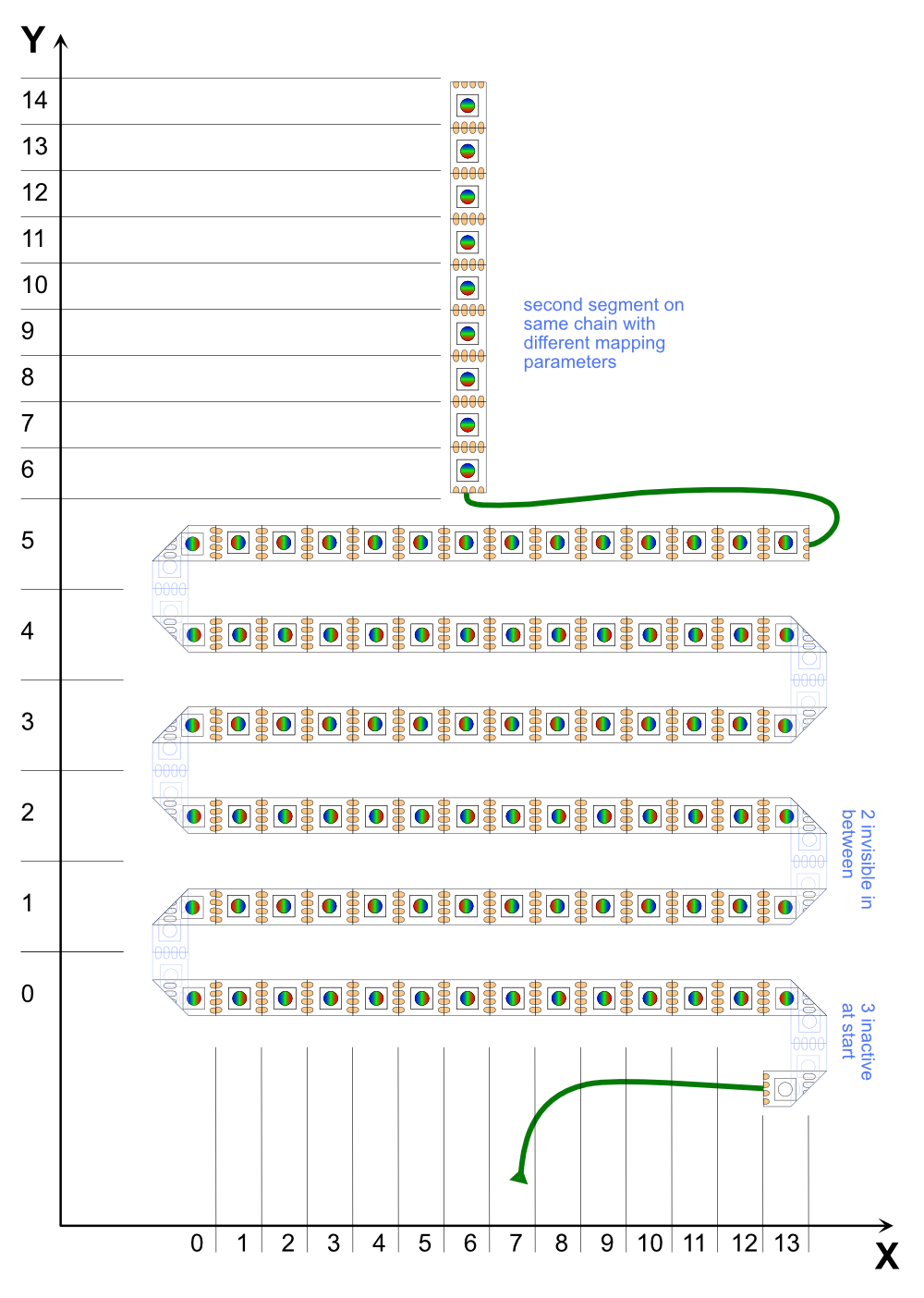
Here we see a chain of 106 LEDs, which has 3 inactive LEDs at the beginning, forms a 14x6 area afterwards (with two inactive LEDs in each kink), and at the end puts 9 more LEDs in Y-direction like a candle on the cake.
The 6x14 area can be described like this:
WS2813.GRB:/dev/ledchain0:106:0:14:0:6:3:2:XA
The X flag is necessary because the first line on the X axis goes backwards, the A flag because the line direction changes every line.
Now to put the 9 "candle" LEDs on the coordinates x=6, y=6..14, it needs another initialization string, which refers to another section of the same LED chain (same leddevicename):
WS2813.GRB:/dev/ledchain0:106:6:1:6:9:97:S
Here the first 97 LEDs are inactive (these are covered by the first definition with the 6*14 matrix). Because the LEDs in this section run in Y direction (instead of X), it needs the S flag.
Use on the command line
For devices and installations with a fixed LED layout, e.g. if the LEDs are an inseparable part of the device, it may make sense for the layout to already be defined when the device is started. In this case, an LED chain initialisation string and additional parameters for power limitation or timing can be passed directly on the command line:
vdcd --ledchain WS2813.GRB:/dev/ledchain0:200 --ledpowerlimit 6000 --ledrefresh 20
The option --ledpowerlimit xx limits the total consumption (approximately) to xx milliwatts by dimming all LEDs accordingly if the pixel pattern to be displayed requires too much brightness. This only works correctly if both the LED type and the actual number of LEDs connected are specified correctly.
The option --ledrefresh yy can be used to specify the minimum refresh interval yy in milliseconds. For very long LED chains, this may need to be set higher to prevent flickering.
In this way, a default arrangement for LED chains is usually predefined in P44-xx devices with LED output. For example, in the Raspberry Pi image P44-DSB-X, a LED chain of 255 LEDs WS2812/13 with GRB layout is defined by default at GPIO18, which is sufficient for simple light strip lighting, for example.
However, if no LED chain is to be defined at the start (but only later with p44script, see below), this is possible by specifying none:
vdcd --ledchain none
Use in p44script
As soon as the LED layout becomes more complex, the definition can also be made using p44script. To try out the correct definition of the sections first, this can also be done interactively and several times in succession in the REPL/IDE. Once the correct layout has been found, the setup can be copied to mainscript so that it is executed each time the device is started. There are a number of functions for managing LED chains, see Script reference.
A typical setup sequence in the mainscript can look like this, for example:
// delete existing definition
removeledchains()
// three chains that together form a narrow rectangle of 600*3 pixels
addledchain("WS2815.RGB:/dev/ledchain0:800:0:600:0:1")
addledchain("WS2815.RGB:/dev/ledchain1:800:0:600:1:1")
addledchain("WS2815.RGB:/dev/ledchain2:800:0:600:2:1")
// adjust the size of root-view
lrg.configure(ledchaincover()).set("fullframe",true) // Output the configuration of the root view for checking lrg.status()
The rootview itself is not changed by changing the LED chain arrangements, not even in size. Thus, the lrg.configure(...)\ command is needed to adjust the size of the rootview to the new arrangement (i.e. corresponds to the outline rectangle ledchaincover(), which covers all defined LED chain sections)
To then see whether the LEDs are all working, the background colour of the root view can be set, for example:
lrg.set('bgcolor','#800') // entire background red (half brightness)
lrg.set('bgcolor','#000') // off again
View configuration
As described above, there are different view types. Each view type has certain properties built in (according to its type), but all views must be configured, e.g. in their size, position, colour, etc. When lrgraphics was developed (for this project), there was no p44script yet, and the entire configuration of the views was defined in JSON files. Therefore, an entire view hierarchy can still be completely expressed in JSON and loaded into the root view.
With p44script the view properties became more directly accessible, first with makeview(), configure() and set() and since firmware 2.7.0.x/1.7.0.x by the fact that views are directly objects in p44script and the properties are available as object fields.
The examples in this documentation therefore use one or the other type of access to view properties.
JSON configuration
There are a few ways to read JSON configuration directly from a file, without p44script (e.g. by specifying a file name when creating an LEDChain luminaire in the "Feature config" field, see also Examples). Usually, however, the configure() function is used to read configuration formulated in JSON:
lrg.configure({ "bgcolor": "#300" })A property of the rootview, bgcolor, is set here.
The status() function can be used to retrieve and inspect the status of a view. As lrg represents the rootview, you can use
lrg.status()to retrieve the entire current view hierarchy.
The set function used above basically does the same as configure(), but is more practical for setting individual values:
lrg.set("bgcolor", hsv(120,0.4,0.5))Here, the colour value (light green) is calculated with the hsv function from the colour wheel angle (hue, 120°), the saturation (40%) and the brightness (50%).
The JSON representation is convenient for defining and importing more complex setups as a whole. For example, a scrolling text requires a scroller in which a text is integrated. On P44-LC-xx devices there is a corresponding configuration as a resource called plan44text.json, so a ticker example can be generated with:
var ticker = makeview("plan44text.json")To make the ticker (or any other view created with makeview) visible, it must be added as a layer to the rootview (which is of type stack):
lrg.addview(ticker)This makes the ticker visible, or at least the part of it that is actually covered by LEDs. The example configuration has a size of 20 x 10, so at least 10 rows of 20 LEDs are required for this case.
To see the content of the JSON and use it in a customised way if necessary, the content of the file can be retrieved:
// Fixed, endlessly repeating ticker
readfile('+/plan44text.json')

// Template for ticker display with any content (on the "CONTENT" stack), repeating endlessly
readfile('+/repeatingticker.json')

// Template for scrolling display, which is programmatically fed by changing
// input with `on(scroller.empty()) { ... }`
readfile('+/ondemandticker.json')
Direct access to view properties as object fields
Since firmware 2.7.0/2.7.0.34 (or 1.7.0/1.7.0.34 for P44-LC) the views are mapped as structured objects in p44script, so they can also be assigned directly, which is even easier than using set():
lrg.bgcolor = hsv(120,0.4,0.5)The current values can also be retrieved separately:
log("The background colour is currently %s", lrg.bgcolor)The status() function is also usually no longer necessary, instead of writing lrg.status() it is now sufficient to simply enter in the REPL of the IDE console:
// entire view hierarchy
lrg

// a specific view based on its label
lrg.findview('labelname')

// the view of an LEDChain luminaire named 'lamp'
device('Lamp').view
View properties
Common properties
All views, including plain, have the following properties:
type- this property is read-only and specifies the view type as a string. If new views are created with
makeview()orconfigure(), this property must be set to the desired view type in the configuration. label- a string to give the view a name - with this name the view can be found again in a hierarchy with
findview(). id- a string that identifies the view instance (i.e. the currently existing version in memory), in a form such as 'V_7758DBC0', with which the view can also be found with
findview(). The ID is different after each restart or recreation, so it is only suitable as a temporary identifier (used internally by the LED simulator, for example). The id cannot be set. To make views persistently retrievable, there is the label, see above. alpha- The opaqueness of the entire view. 0=completely transparent, invisible, 255=completely opaque Note: an opaque view (alpha=255) can also contain partially or completely transparent pixels. The transparency of the entire view is combined with the transparency of the pixels in the display. If "Ledchain" luminaires are defined in the P44 web interface, the "alpha" property is controlled by the brightness control of the luminaire.
visible- Returns true if alpha is not zero, otherwise false.
- If visible is assigned a value that is not false, alpha is set to 255, otherwise to 0.
bgcolor- The background colour of the view, i.e. the colour of all pixels on which no content is displayed.
-
The colour is specified as a string in web colour format. The following formats are supported:
#rrggbb- where rr,gg,bb are two-digit hexadecimal numbers 00..FF (decimal: 0..255), which represent the colour components rred, ggreen and bblue.
#rgb- this is a shorthand notation for #rrggbb, i.e.
#123means#112233. #aarrggbb- like #rrggbb, but aa is a fourth hexadecimal number 00..FF (decimal: 0..255), which specifies the alpha value (the opacity). If the alpha value is not specified, it is assumed to be FF (=opaque).
#112233is therefore equivalent to#FF112233. #argb- this is a shorthand notation for #aarrggbb, i.e.
#D123means#dd112233.
color- The foreground colour (in the same format as bgcolor). For views of type plain, this is the colour in which the content rectangle (see below) is displayed. For other view types, color is either used as the base colour for the display (lightspot, torch, text) or is not relevant because the content has its own colours (image, stack, scroller, sequencer).
- If "Ledchain" luminaires are defined in the P44 web interface, the
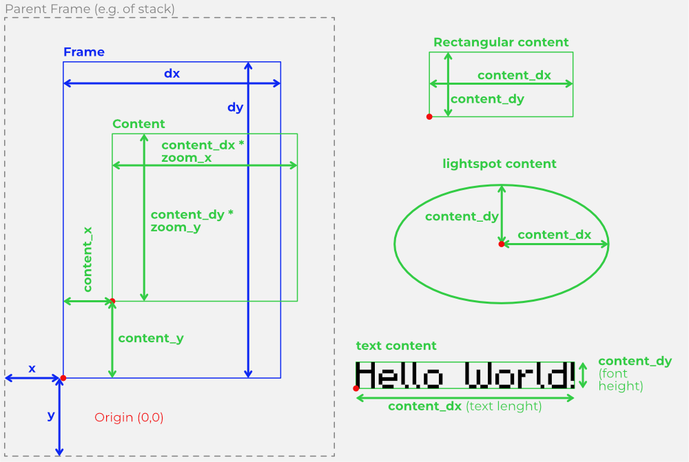
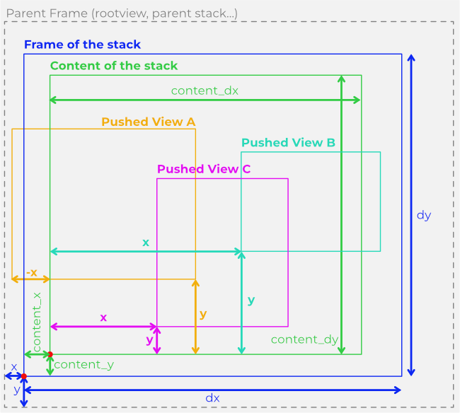
colorproperty is controlled by the colour sliders of the luminaire. x, y, dx, dy- These four values form the frame for the view.
- x and y indicate where the bottom left-hand corner of this view is positioned in relation to the parent view.
- dx and dy specify the width and length of the frame.
content_x, content_y, content_dx, content_dy- These four values form the content (content) rectangle of the view.
- content_x and content_y indicate where the zero point of the content is positioned in relation to the zero point of the frame (for rectangular content, the bottom left corner).
-
content_dx and content_dy specify the size of the content. For rectangular content, this is the width and length of the outline rectangle, but it can also be another meaningful dimension, e.g. for lightspot it is the half-axis of the light spot ellipse. Depending on the view type, the content size is also determined indirectly by the content, for example in image or text views. In the plain view, this simply defines the rectangle that is to be displayed in the foreground colour (color).
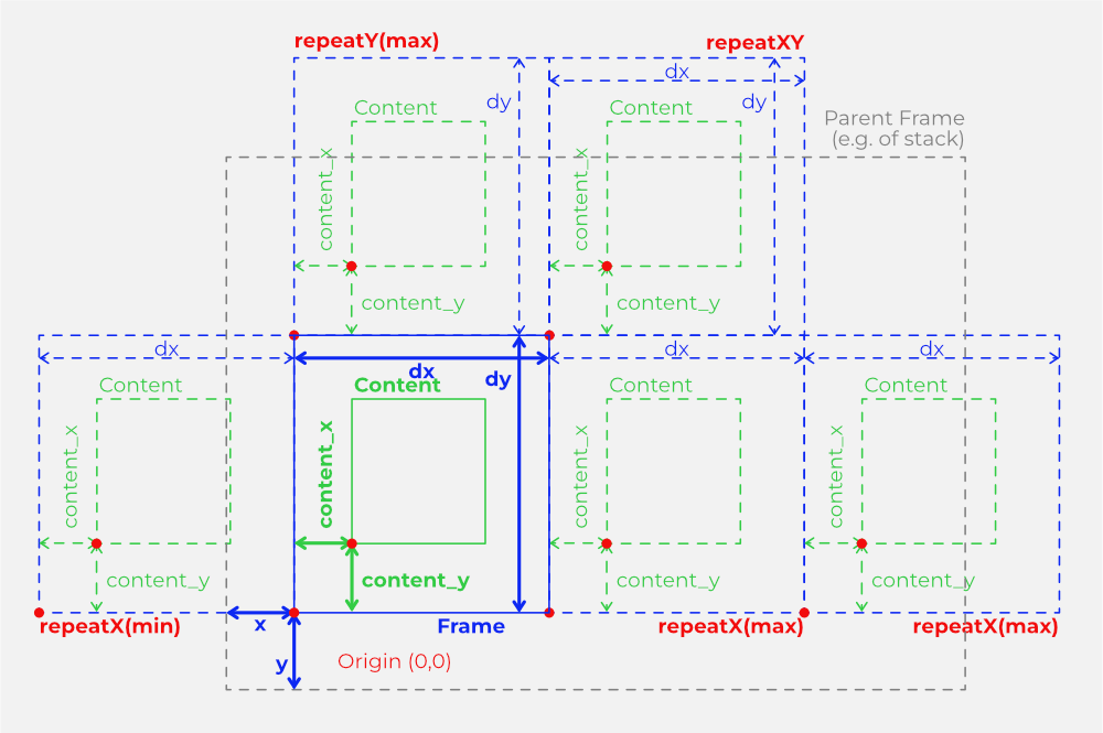
framing-
This property determines how the framing works. It is a string in which one or more (separated by
|, no spaces!) of the following flags are specified:none- No framing, the content is neither clipped nor repeated
clipXmin, clipXmax, clipX, clipYmin, clipYmax, clipY, clipXY- Content that extends beyond the frame is clipped by the frame. This can be specified separately for each side of the frame (Xmin, Xmax, Ymin, Ymax), for one direction (X,Y) or for the whole frame together (XY).
repeatXmin, repeatXmax, repeatX, repeatYmin, repeatYmax, repeatY, repeatXY.-
The content of the frame is repeated in the specified direction(s). This allows background patterns or "endlessly" repeating scrolling fonts etc. to be realised.
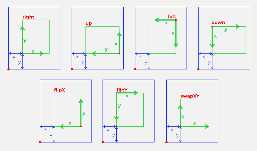
orientation- This determines the basic orientation of the content in relation to the frame and allows the content to be mirrored and rotated in 90-degree steps.
- This property is used to determine the basic orientation of the content in the pixel grid. With rotation, scrollX,Y and zoomX,Y the display can be customised more precisely.
-
The value is a string in which one or more (separated by
|, no spaces!) of the following flags are specified:right- the "normal" orientation, X-axis horizontal from left to right and Y-axis vertical from bottom to top.
left, down, up- Other directions of the X-axis
swapXY- X and Y coordinates swapped
flipX, flipY- X or Y coordinate mirrored
rotation- Rotation angle in degrees (0..360) by which the content is to be rotated around its zero point (content_x, content_y), clockwise
scroll_x, scroll_y- Shift of the content relative to its zero point (content_x, content_y). The shift is applied after the rotation, i.e. the X scroll direction is rotated by the angle specified in rotation relative to the horizontal. This can be used to realise slanted tickers, for example.
- The scroll values do not have to be integers, it is possible to shift the content by fractions of pixels (subpixels). The graphics system calculates the resulting pixels as the average of the cropped pixels (anti-aliasing).
zoom_x, zoom_y-
Enlargement factor for the content, or reduction factor if <1.
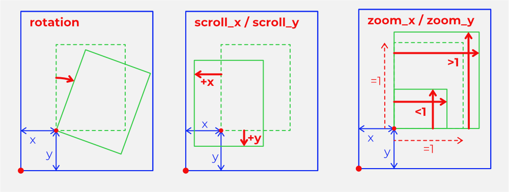
Subpixel calculation needs performance
Non-integer values for scroll_x/y, values not equal to 1 for zoom_x,y and values not equal to 0 for rotation switch on a more complex pixel calculation, which must include different proportions of content pixels for a displayed pixel and therefore requires additional performance. These settings should therefore only be used if it makes sense visually.
timingpriority- If this value is set to true, the view has "timing priority", i.e. changes occurring on it are displayed as immediately as possible.
- This can be problematic with nested scrollers or animations on scrollers, because the two movements combined require an excessively high update rate of the LEDs, which the hardware cannot implement - the result then looks jerky. In such cases, timingpriority can be set to false in subordinate views so that the higher-level movement, e.g. a scrolling text, determines the update rate alone and thus appears smooth. The timing of subordinate movements is then adapted to the superordinate, prioritised timing, i.e. it is no longer completely exact - but this is not noticeable in fast scrollers (in contrast to the jerking of the scroller itself if it has no priority).
subsampling- If this value is set to true (which is the default), the colours for a displayed pixel with non-integer scroll_x,y, zoom_x,y!=1 or rotation!=0 are calculated from the area proportions of the affected content pixels, which results in a nicely continuous display. However, this calculation is relatively complex and can be switched off with subsampling=false. Whether this makes sense depends on the desired look - but with nested views, for example, it may be sufficient for the topmost view to subsample, if the nested views do not do this, it may be less visible, but saves performance.
invertalpha- If this value is set to true, the transparency component of the content pixels is inverted. This can be used especially in combination with
contentismask contentismask- If this value is set to true, only the transparency portion of the content pixels is used, the colour of all pixels is taken from the color setting. This allows, for example, an image or text to be used as a mask to cover certain pixels of a view behind it (in a stack) and allow others to shine through.
sizetocontent- If this value is set to true and the content rectangle is changed, the frame size (dx, dy) of the view is adapted to the content. This can be useful for views where the content determines the size (images, text).
autoadjust- If this is not
none, then this view is adjusted in position and size when the parent view (stack, scroller or sequencer) changes its geometry. -
The value is a string in which one or more (separated by
|, no spaces!) of the following flags are specified:none- (default value) no automatic adjustment.
fillX, fillY, fillXY- Size is adjusted to the size of the parent view in the corresponding direction
noadjust- If this flag is also set, the frame is adjusted, but the content is not subsequently set to the size of the frame.
z_order- This value only has a meaning if the view is a subview of a stack. Then the subviews are placed on top of each other in the order of z_order, the subview with the highest z_order is the foremost (and, depending on transparency, covers the ones behind it).
Common methods
In p44script, views are objects that also have some methods:
configure(json),configure(resource_file),set(prop, val),findview(viewlabel),addview(view)parent(),remove(),animator('propertyname'),stopanimations(),reset(),clear()- These are the basic methods for working with views from p44script, and are described in the p44script short reference together with the global functions for controlling LED chains.
For the following, let v be a view:
v.render()- Triggers an update of the LED display. Normally this happens automatically, the function exists mainly for debugging purposes.
v.fullframe()- Adjusts the content rectangle so that it fills the entire frame.
v.content_position(rel_x, rel_y, centered)- Positions the content rectangle relative to the size of the frame. rel_x and rel_y specify the position within the frame in the range -1 to 1, values >1 or <-1 move the content out of the frame. If centered is true, then the centre of the content rectangle is positioned, otherwise the origin (bottom left corner). rel_x or rel_y can also be passed as null if the corresponding coordinate is not to be changed.
v.content_size(rel_dx, rel_dy)- Adjusts the content size relative to the size of the frame. rel_dx and rel_dy specify the scaling factor for width and height separately in relation to the frame; if both are 1, the content is given the same size as the frame. rel_dx or rel_dy can also be passed as null if only one dimension is to be resized.
v.get(x, y)- Reads the current colour value of the pixel at position x, y (in frame coordinates, i.e. relative to the bottom left corner).
v.animations()- Returns an array with all animators active on the view.
Colour Effect
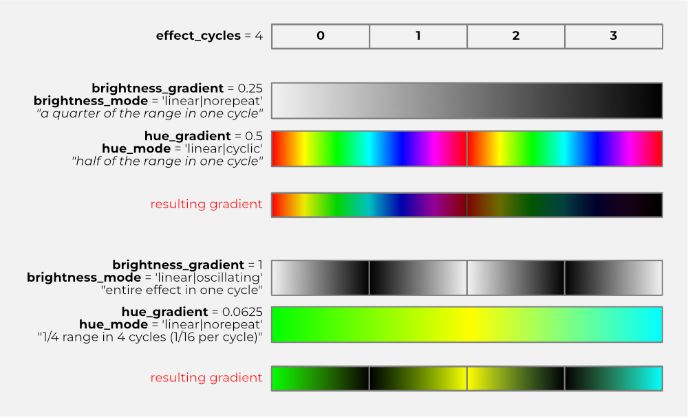
There is no separate "Color Effect" View, but lightspot, canvas and text are based on the same "Color Effect" colour gradient generator, which has the following properties:
brightness_gradient,hue_gradient,saturation_gradient- Proportion of the full scale (0..1 for saturation and brightness, 0..360 for hue) by which the corresponding value should change in an effect cycle (see
effect_cycles), starting from the set foreground colour (color).
brightness_mode,
hue_mode,
saturation_mode
Behaviour of the respective colour component in the gradient. The value is a string in which one or more (separated by |, no spaces!) of the following flags are specified:
`none`
switched off, colour component is not changed in the course of the gradient.

`square`
: Rectangular transition at 50%.

`linear`, `sin`, `cos`, `log`, `exp`
: Curve shape of the transition.

`norepeat`, `cyclic`, `oscillating`, `unlimited`
: Repetition options of the curve.

`inverted`
: Inversion of the curve shape.
effect_cylces-
How many cycles are used to calculate the gradient over the size of the content. This can be used to achieve repetitions for wavy colour effects etc.
The following illustration shows the composition of two different gradients:
transparent_fade- if true, then the brightness component (
brightness) controls the transparency of the pixel, i.e. at zero brightness the pixel becomes transparent, otherwise the pixel remains opaque and becomes black at zero brightness (opaque). radial- how the colour effect "spreads": If true, then the gradient is used radially from the content origin, i.e. the gradient depends on the distance to the origin and therefore looks circular/oval. Otherwise, the effect spreads along the x-axis.
effect_zoom- Scaling/limitation of the visible effect in relation to the content size. If negative, the zoom is infinite or the effect expands as far as the framing of the view allows.
effect_wrap- If true, the effect is repeated with a larger zoom, otherwise the colour remains at the end of the effect.
Lightspot
Lightspot is based on the ColorEffect (see above), and uses the gradient to create a "light spot". Unlike most rectangular views, lightspot uses the size specifications of the content (content_dx, content_dy) as radii (half-axes) for the light spot effect (extension of the gradient).
However, effect_zoom can crop (<1) or expand (>1) the effective size of the light point, and can be regarded as a kind of "aperture".
Text
The text view can display a text in pixel font in various fonts and with the colouring options of the color effects, e.g. with a colour gradient. If no colour effect is configured, the entire text appears in the foreground colour (color).
text- String for the text to be displayed. Not all fonts support all special characters, unknown characters are displayed as a rectangle. The text is always single-line, control characters are displayed as unknown characters.
font- Name of the font to be used. The following fonts are built-in:
3x3,5x5,5x7,5x8,m3x6,m5x7,m6x11,bios,sixtyfour,vcr_osd_mono. Additional fonts can be loaded from.lrgffiles usingloadfont. The names of all currently available fonts can be retrieved using the p44script functionlrgfonts(). spacing- Number of empty pixels between two characters. Default = 2.
bolden- If >0, a bold font effect is created by shifting the font template bolden by one pixel at a time.
stretch- If >0, each pixel column of the font template is repeated stretch times, which stretches the font.
collapsed- If set to true, the text (and the content rectangle) collapses to zero size and therefore becomes invisible. In contrast to
visible==false, this changes the size, which can play a role in consecutive text views. loadfont(fontname)- Loads a font from a
.lrgffont file (which is a simple format based on p44utils TLV serializer and can be produced by the FontHexer2 app).
Canvas
A canvas view is a drawing area on which the colour of each individual pixel in the content rectangle can be set individually. If the size of the content rectangle is changed, all pixels are deleted (made transparent). Pixels outside the content rectangle appear in the background colour (bgcolor)
dot(x, y)- This method sets the pixel at the content coordinate (x, y) to the currently set foreground colour (see
color). line(x0, y0, x1, y1)- Draws a straight line from (x0,y0) to (x1,y1). The pixels of the line are set to the currently set foreground colour (see
color) or, if configured, displayed with the colouring options of color effects, e.g. with a colour gradient along the line. copy([sourceview ,] x, y, dx, dy, dest_x, dest_y [, transparentonly [, fromcontent])- copies the pixels in the rectangle (x,y,dx,dy) from the canvas itself, or if sourceview is specified, from another view, to the point (dest_x,dest_y) in the canvas. If transparentonly is set, fully transparent pixels will not be copied. If fromcontent is set, the source rectangle specifies content coordinates instead of frame coordinates, so source pixels are not affected by content offsets, zooming, scrolling and rotation.
pixels- returns the number of pixels of the character area (content_dx * content_dy)
bytes- returns the number of bytes that the drawing area occupies in memory.
Image
This view type can load and display a PNG image. - If the content size is smaller than the image, it is cropped accordingly at the top and right. - However, if the content size is set larger than the image, then the top pixel line of the image is duplicated upwards and the one on the right edge is duplicated to the right. This means, for example, that a striped pattern can be drawn as a space-saving image 1 pixel high, but can still fill a larger area.
loadimage(filepath)-
This method reads a PNG image from the specified filepath into the view and sets the size (content_dx, content_dy) according to the size of the image.
Attention, memory requirement
A loaded PNG image requires 4 bytes in memory for each pixel. If large images are loaded, the application can quickly reach its memory limits. With the low resolution of an LED pixel display, large images are also not useful. It is recommended that PNG images to be used are scaled down exactly to the required resolution in an image editing programme before they are used (even if scaling is possible within lrgraphics using
zoom_x/zoom_y). -
Without an absolute path or special prefix, filepath is interpreted as relative to the p44script resource directory (a directory in the non-writable area that contains some predefined images). The following special prefixes can be used:
_/tempfile: means that tempfile is to be used relative to the (full) p44script temporary directory.+/file: means that file is to be used relative to the writeable p44script data directory in the application's flash memory.
image_dx,image_dy- read-only, indicates the effective size of the loaded image.
bytes- read-only, indicates the memory requirement in bytes of the loaded image.
Stack
The stack is a so-called container view, i.e. it contains other views that determine its content. Each of these subviews is displayed based on its frame origin (x, y) relative to the origin of the content of the stack. If the views overlap, then z_order determines the order in which the views are stacked on top of each other.
A frequent use case for LED displays are tickers, which is why the stack not only supports stacking, but also the automatic lining up of parts, as is necessary in a ticker/graphic that is continuously fed with new content, and also the automatic removal of parts that have already been scrolled out of the field of vision in a scroller (see also there) and are no longer required.
layers- An array containing the layers of the stack, sorted in ascending order according to their z_order ("foremost" view last in the array). This array cannot be changed directly, only via pushview(), addview(), popview() etc.
positioningmode-
Determines the positioning of views that are added with pushview() or addview(). The value is a string in which one or more (separated by
|, no spaces!) of the following flags are specified:appendLeft,appendRight,appendBottom,appendTop- Newly added views are appended to the views already in the stack on the specified side.
- With purge(), the views on the opposite side that lie outside are removed, i.e.: when appending on the right with appendright, the views lying furthest left are removed with purge().
noAdjust- If this flag is set, the content size is not changed, even if the frame size changes
fillX,fillY,fillXY- These flags cause newly added views to be set equal to the content size of the stack in width, height or both in order to fill it.
pushview(view [,spacing [, fullframe]])addview(view)- Adds the view to the stack content. addview(view) is the same as pushview(view, 0, false).
- It depends on positioningmode how the view is positioned. If positioningmode is
noneornoAdjust, then the view is simply set to the position (relative to the content origin of the stack) specified by view.x and view.y. If a positioningmode is selected, in which views are lined up, spacing specifies the number of pixels between them. If fullframe is set, then the content of the added views is adapted to the frame (this is useful if the frame of the added views gets changed, e.g. because of positioningmode == 'fill...', and the content should be adapted accordingly). popview()- removes the "foremost" subview from the stack. This is not necessarily the last one added, but the one with the highest z_order, as the stack is always stacked in this order.
- To remove other positions, the remove() method of the view to be removed must be called.
purge(dx, dy, completely)- Removes all subviews from the stack that do not have space within the rectangle (dx,dy) (except for one - the last view in the stack is never removed, even if it does not have space). The rectangle is measured from the edge specified with append... in positioningmode, so the views are removed on the opposite side. This is the mechanism you need for continuous content in a ticker.
- If completely = true, only views are retained that fit completely within (dx,dy), otherwise also those of which at least a part is still within (dx,dy).
- The purge mechanism can also be used by the scroller to automatically remove scrolled-out, no longer required content from the stack, see there.
Scroller
A scroller can continuously scroll another view, the scrolledview, by automatically increasing or decreasing its own scroll_y and scroll_y properties in a certain time interval.
With scroller, the content that is moved with scroll_x,y (possibly also scaled beforehand with zoom_x,y and rotated with rotation) is an entire view. In particular, this means that for endlessly scrolling content, the framing of the scrolledview can be set to repeatX, for example, so that even a small scrolledview becomes an (almost) endlessly long band with repeating content.
However, because the scroll offset would become larger and larger with a simple count-up, scroller also has a mechanism that "rewinds" the scroll offset from time to time, but in such a way that this is completely invisible (by "rewinding" by an integer multiple of the content). This is usually irrelevant when using scroller, but if the current scroll_x,y is queried, you must be aware that it can also jump backwards to the scroll direction occasionally.
The visible scroll speed consists of the number of pixels (also fractions) of movement per step (step_x, step_y), plus the time interval (interval) between two steps. At slow scrolling speeds (less than 1 pixel per 50mS) it is advisable not to increase the interval, but to make the steps smaller (<1, subpixel) - because then continuous transitions are calculated and give the impression of smooth movement, rather than slow pixel-by-pixel hopping.
For tickers/graphics with changing content, such as a news ticker etc., scroller can send an event via empty()/alertempty() when the "supply" of content (views on a stack, see pushview() and positioningmode in the stack view) runs out. A handler on(v.empty()) { ... } can then be used to provide new content at the right time.
scrolledview- this is the view that is scrolled. This can be a simple view, or a stack if the content to be scrolled itself consists of several views (e.g. graphics + text mixed).
step_x,step_y- Change of scroll_x or scroll_y that is to take place per interval.
interval- Time interval between two scroll steps (in seconds)
steps- Number of remaining scroll steps, read-only. If scrolling was started with a fixed number of steps (see startscroll()), this value indicates how many steps remain until the stop. If this value is 0, the scroller is stopped (see stopscroll()). If the value is negative, the scroller runs without limit until stopscroll() is called.
syncscroll- If this value is true, then the scroll distance is synchronised exactly over time, i.e. if the system does not keep up with the image calculation due to temporary overload (e.g. due to other system activities), then the scroller can "jump" forwards to make up for a delay. This is important, for example, if several devices are controlling a common large ticker and the scroll distances must therefore not drift apart due to such disturbances. If syncscroll is switched off, the scroller does not try to catch up and there are no "hops", but there are time deviations (which is usually not a problem with a single scroller).
autopurge- If this flag is true and the scrolledview is a stack, then the scroller automatically uses the purge() mechanism of the stack to remove those views that have scrolled out of the image. This is very practical for a ticker with constantly changing content - it only requires an empty() handler (see below), which produces new views "on demand"; autopurge takes care of the disposal automatically.
For the following, s is a scroller:
s.startscroll(stepX, stepY, interval)s.startscroll(stepX, stepY, interval, roundoffsets [,numsteps [,syncstart]])-
- Starts the scroller with corresponding values for step_x, step_y and interval.
- If roundoffset is not false, then scroll_x and scroll_y are rounded to integer pixels before starting.
- If numsteps is specified and is greater than 0, the scroller runs the specified number of steps and then stops.
- With syncstart either an absolute time (as seconds since 1.1.1970, see epochtime()) or, if <86400, a synchronisation time such as "at the next full quarter of an hour" (_syncstart = 1560) can be specified at which the scroll starts. This is useful for starting several scrollers, which may be distributed across different devices, at exactly the same time. If syncstart* is not specified, the scroller starts immediately.
s.stopscroll()- Stops the scroller immediately.
s.purge()- calls the purge(dx,dy) method on the scrolledview (if this is a stack), with dx/dy so that views that already have scrolled past are removed. If autopurge is set, this happens automatically and purge() does not have to be called directly.
s.remainingpixels()- returns an object with two fields x and y, which indicate how many pixels the scrolledview still has "in reserve" before the scroller starts to empty (because there is nothing left). Negative values indicate how many pixels are already empty because nothing follows. If the reserve is "endless", either because there is no scrolling in that direction or because the scrolledview has a framing with repeatX/Y, then the corresponding field is null.
s.remainingtime()- calculates how many seconds the scroller still has "stock" (see also remainingpixels()) before it starts to empty, or if negative, how much time ago the stock ran out. If the scroll content is endless (due to repeatX/Y), null is returned (before x.7.0.37: -0.000001).
s.empty()-
returns true when the supply of display material (which becomes visible again when scrolling) is exhausted, i.e. exactly when remainingtime() becomes zero. However, the special feature of empty() is that it is an event source, which can be used in a handler with
on(v.empty()) { ... code ... }to execute code that produces new content and adds it with pushview() the moment the scroller runs out of content:// Assumption: a 'Ticker' light exists, which has been configured with the // "feature config" "ondemandticker.json" was created. var scroller = device('Ticker').view on (scroller.empty()) { // Create new text view with current date/time var t = makeview({ type:'text', text: " +++ It is now " + formattime(), // Date / time colour: hsv(random(0,359,1)), // Random colour sizetocontent: true }) // Add scroller.scrolledview.pushview(t) // From now on warn again if once more empty scroller.alertempty(true) } // Call handler if view is empty scroller.alertempty(true) scroller.startscroll(1,0,0.05) s.alertempty(enable)- In order for empty() to trigger an event, the mechanism must be "armed" with alertempty(true). Otherwise the handler would be called constantly unless enough content is loaded immediately (which may not be possible). As soon as the handler has been called once, alertempty is automatically set to false and must be enabled again for the next "round" - e.g. as the last action in the handler (as shown in the example above).
Sequencer
The sequencer is a view that can show/hide a number of other views one after the other like a slideshow. To do this, pushstep() can be used to add views together with a display time and optionally a fade-in and fade-out time. The sequence is started with start.
steps- This field is read-only and returns an array with the current steps of the sequencer, each as an object with 4 fields view, showtime, fadeintime, fadeouttime.
For the following, let s be a sequencer:
s.pushstep(view, showtime [, fadeintime [, fadeouttime]]- Adds another step. view is the view to be shown, showtime is the display time in seconds.
- Optionally, a fade-in and fade-out time (fadeintime, fadeouttime) can be specified, within which the alpha of the view is moved between 0 and 255.
s.start()s.start(repeat)- Starts the sequence. If repeat is true, the sequence runs in a loop until it is stopped. Otherwise, the sequence stops automatically after the last step.
s.stop()- Stops the sequence, but not running animations on the displayed view, especially not a running fade-in or fade-out animation.
s.stopanimations()- Stops the sequence and all animations on the currently displayed view.
EPX (Expressive pixels)
Expressive Pixels is a format for LED pixel animations from Microsoft Research that was introduced with much fanfare in 2020. It is easy to implement and basically suitable for pixel matrices such as p44lrgraphics, which is why the epx view exists. Unfortunately, the project has completely fallen asleep at Microsoft, nothing has happened at all since 2020. The Windows app should still exist.
The epx view can read and display "expressive pixel" animations in JSON format. The width of the content (content_dx) must be set to match the width of the epx, the JSON format does not contain this information.
run- This property must be set to true to start the animation. It automatically returns to false when the animation ends.
loadepx(json)loadepx(jsonfile)- loads an Expressive Pixels animation either from the directly specified (JSON) object, or if a filename is passed, from the corresponding file.
Life (Conway's Game of Live)
Represents Conway's "Game of Life". Initially the field (content_dx,dy) is empty, addrandom() or placepattern() must be called once for something to become visible.
generationinterval- Time between two cell generations in seconds.
minstatic- How many cycles no movement on the field may occur if the number of cells is below minpopulation before some cells are automatically set. This value is used to quickly add new cells when the field is empty or almost empty so that it does not get boring.
maxstatic
How many cycles no movement may occur on the field if the number of cells is above minpopulation before some cells are automatically set. This value is used to leave a field with possibly interesting static patterns for a while before new cells are scattered.
- minpopulation
- The number of cells below which the minstatic value applies.
addrandom()addrandom(max)addrandom(min, max)- Randomly scatters new cells approximately in the specified number, or without specification automatically suitable for the field size, in order to revitalise the game.
placepattern(pattern)placepattern(pattern, x, y, orientation)- places a predefined (well known) pattern on the field. pattern can be one of the following strings:
dot,blinker,toad,beacon,pentadecathlon,rpentomino,diehard,acorn,glider. - x and y indicate where the centre of the pattern is to be placed; if not specified, it is placed randomly. The orientation can be a value from 0 to 3 for the 4 possible orientations.
Torch
The "Torch" is a simple fire animation that creates a pretty "torch" with an LED chain wound on or in a cylinder. The torch is available as a P44-LC-TORCH to buy as a kit or can be built with a RaspberryPi.
torch has a lot of parameters, you can also change the animation by experimenting so that it can be used as a rain simulation or similar ;-) Basically it is a kind of spark simulation, each point has a certain amount of energy and transfers this upwards and sideways in each cycle, and loses energy. The points are then coloured according to the energy with the underlying coloreffect gradient.
cycletime- [default: 0.025] Cycle time for the animation in seconds.
flame_min- [default: 100] Minimum energy in the "flame" (bottom rows).
flame_max- [default: 220] Maximum energy in the "flame" (bottom rows).
flame_height- [default: 1] Height of the "flame" (how many bottom rows).
spark_probability- [default: 2] Probability that a "spark" will be released upwards from the "fire".
spark_min- [default: 200] Minimum starting energy of a spark.
spark_max- [default: 255] Maximum starting energy of a spark.
spark_tfr- [default: 40] Amount of energy (percentage: 0=nothing, 255=everything) that the spark carries upwards.
spark_cap- [default: 200] Amount of energy (percentage: 0=nothing, 255=everything) that the spark itself retains.
up_rad- [default: 40] Radiation upwards.
side_rad- [default: 35] Radiation sideways.
heat_cap- [default: 0] "Heat capacity" of the invisible points.
hotspark_min- [default: 250] Threshold value for the display as a "hot" spark.
hotsparkcolor- [default: '#AAAAFAFF'] Colour for "hot sparks". Normal sparks have color as base colour with the gradient according to coloreffect.
hotsparkinc- [default: '#000005FF'] Additional colour for maximum hot (255) point.