P44-DSB - Information for installation and support
Attention - Uncorrected machine translation
This English version of the following text is currently 100% machine translated. In case of ambiguity, please refer to the German version (which in this case is the original written by hand).
This documentation page is intended for supporters and installers, and provides useful information for planning, installation and maintenance.
The following quick links refer directly to particularly important topics, otherwise the table of contents (displayed on the left as a column if the browser page is wide enough, on the mobile at the top) gives an overview.
Quick links to important topics
Systematic troubleshooting:
- Procedure in general.
- Procedure for DALI problems.
Power supply:
- Power supply: which power supplies, notes on PPoE
P44-DSB is not displayed or not reliably displayed in the dSS:
- LED on the P44-DSB: check device state.
- Network connection between dSS and P44-DSB should go through simple (dumb) switches.
- P44-DSB was in use with this dSS before, but was disabled → enable again.
- There are/were multiple dSS in use on the same network → may cause problems.
- The P44-DSB has been changed to a fixed IP address once before → factory reset, if possible better use DHCP.
Call the web interface of the P44-DSB remotely:
- Direct access to P44-DSB-E, P44-DSB-E2, P44-DSB-DEH2, P44-DSB-D via plan44 pagekite.
- Access to web interface of P44-DSB (also old P44-DSB-DEH) via ssh tunnel and Digital Strom.
Too much/too little visible in the log:.
- Loglevel adjust to get more or less details.
- Log single device more or less detailed adjust single device.
DALI bus problems:
- Overview/documentation of actual state retrieve.
- Bus voltage and current measure.
- Patience. DALI is slow, scans take a long time.
- New commissioning: proceed systematically especially if devices without unique serial number are in use!
- Extend DALI installation: proceed systematically especially if devices without unique serial number are in use!
- Device selection: massively less problems with dimmers/drivers with unique electronic serial number!
Enocean problems:
- signal strengths check
- Patience. EnOcean devices (e.g. heating valves) may not respond immediately
Get support from plan44:
- Best by email or support form, with enough details
Power supply
Power supply via plug-in power supply unit.
A suitable plug-in power supply unit is supplied with each P44-DSB.
-
The P44-DSB-DEH (first model, not the P44-DSB-DEH2) requires a power supply with 12-18V, round plug, positive pole inside, at least 800mA current capability. If the P44-DSB-DEH appears to be defective (LED still lights up yellow, but no access and no function), in most cases the power supply unit is defective (not completely, but so weakened that only the LED lights up, but the unit cannot start). Most commercially available WLAN routers have such power supplies (usually 12V).
-
All other products (P44-DSB-E2, -DEH2, P44-DSB-E, P44-LC-DE) are supplied via a 5V/1A power supply unit with a micro-USB plug. Almost any power supply with a micro-USB plug is compatible if it has 5W (=1A) output power or more. Even these power supplies can become weak, so that the LED still lights up but the device no longer starts properly.
-
Even if a device is accessible in the network but there are problems with the DALI bus (inexplicable address conflicts etc.), the power supply unit may also be the problem. However, this is rather rare, DALI problems often have other causes, see Troubleshooting tips.
Power supply via Ethernet cable and Passive Power over Ethernet (PPoE).
- The P44-DSB-DEH2, P44-DSB-E2 and P44-LC-DE products can alternatively be powered via Passive PoE (PPoE). PoE is not the same as PoE (as provided by certain Ethernet switches).
- Passive-PoE/PPoE requires a suitable injector and a power supply with the correct voltage, which is included in the P44-PPoE Kit from plan44, for example. Other injectors and power supplies can also be used, as long as the set-up complies with this documentation corresponds.
-
In case of strange DALI problems and PPoE supply: Use plug-in power supply on a trial basis.
Never use PPoE and plug-in power supply at the same time!
This can cause cross currents which, depending on the power supply units involved, can cause damage to them or even cause the supply chip fuse in the P44-DSB/LC to respond (protects the unit from serious defect, but it must be repaired).
Access to the P44 DSB web interface.
For installation and support, access to the P44-DSB device web interface is required. Normally and with a PC/Mac in the local network, this can be accessed via the dSS configurator in the "Hardware" tab, by right-clicking on one of the P44 lines at "Meter & Controller ".
In case of support, however, one often wants to access remotely, or the connection to the dSS does not yet exist. Then the following methods help:
Locating a P44-DSB in the local network.
If the P44-DSB is set to DHCP (which it should be, see network configuration), then the IP address in the LAN router can usually be found in a table of DHCP clients.
However, the P44-DSB always make themselves discoverable in the local network via DNS-SD. DNS-SD is also the mechanism used by the dSS to find P44-DSBs.
Tools with graphical interface:
- for macOS: most convenient for frequent users with the app Localsites from plan44.ch; costs CHF 1 in the Appstore.
- for macOS: free with the app Discovery - DNS-SD Browser by Lily Ballard.
- for iPhone/iPad: free with the app Discovery - DNS-SD Browser by Lily Ballard.
- for Linux using Ubuntu as an example: With the GUI app Avahi Zeroconf Browser.
- for Windows: there is unfortunately still nothing, although DNS-SD has definitely become established (and is also used internally in Windows for printer search etc.).
On the command line:
- macOS and partly Windows, from Windows 10, depending on the installed software.
- with
dns-sd -B _http._tcpretrieve the list of devices, tool must be terminated withCtrl-C. - with
dns-sd -L 'name of the device EXACTLY as in the list' _http._tcpdisplay hostname of the device, something in the formp44dsbe243215672.local. - show the IP address with
dns-sd -G v4 hostname.local.. - Linux, Windows with Windows Subsystem for Linux (WSL) installed:
- with
avahi-browse -t -r _http._tcpshow all devices and their IP addresses.
Remote Access.
Direct to P44-DSB-DEH2, P44-DSB-E2, P44-DSB-D, P44-DSB-E (but not the older model P44-DSB-DEH).
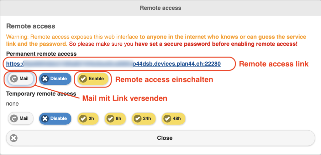
Starting with firmware 2.0.0.0, P44-DSB devices have a direct way to enable remote access in a similar way to dSS:
- The server capacity of plan44.ch is not designed for all devices to do remote access all the time! Therefore the option is a bit hidden in the web interface. Please use it only for support purposes and switch it off afterwards.
- On the tab "System" click the button "Rename..." with pressed
Cmd(Mac) orCtrl(PC) key. -
In the dialog that appears, you can click to enable remote access and send an e-mail with the link. For security reasons this only works if the device has a password other than the default password (as with the dSS).
Indirectly via dSS (also works for the older P44-DSB-DEH).
If Digital Strom remote access to an installation exists, the web interface of connected P44-DSB can also be reached via a so-called ssh tunnel:
- In the dSS under "System" → "System Settings" → "System" → "Access via SSH " must be switched on.
-
From the pagekite remote access URL copy only the hostname (i.e. without
https://and without everything after the first/), e.g.0e77c21a469e42a29de42ec7337adead.digitalstrom.net -
Determine the IP address of the P44-DSB - if not already known: In the dSS under "Hardware" → "Meter & Controller " in the context menu of the P44-DSB move the mouse over the entry "Open configuration interface " (do not click!), note the IP address in the status bar of the browser.
-
Either: On a Unix compatible console (Linux, BSD, Mac OS X, Cygwin, Windows Susbystem for Linux WSL), insert current hostname and IP of the P44:
``bash DSSHOST=0e77c21a469e42a29de42ec7337adead.digitalstrom.net P44DSBIP=192.168.31.54 ssh -l dssadmin ${DSSHOST} -L 8980:${P44DSBIP}:80 ```
-
On Windows with putty: set up a normal ssh connection to the dSS and then a tunnel to it, as follows (press Add at the end):
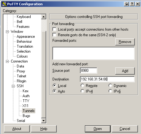
and then establish the connection.
-
On the local PC call the URL
http://localhost:8980, the web interface of the P44-DSB appears.!!! warning "use http, not https". The tunnel is for unencrypted http, so the URL in the browser must not start with https://. This is not a security risk, since the ssh tunnel itself is already encrypted. Moreover, accessing the old P44-DSB-DEH with https would hardly be possible, because infinitely slow.
Network configuration.
Network - to be considered in general
-
A P44-DSB can be connected to only one dSS at a time. If there are multiple dSS on the LAN (which sometimes happens in test environments), they will automatically coordinate that only one will bind the P44-DSB. Which dSS of several this is cannot be predicted. In unfortunate cases (e.g., nervous rapid plugging and unplugging of P44 and or dSSs), it can also happen that two dSSs think they have the connection. Therefore, if several dSSs are in a LAN, always check:
- in both configurators
- in each case in tab "System" → "Access authorization" → "Enable network devices "
- check if the P44-DSB appears there
- make sure that the checkbox "Connection " is only set for one dSS, for all others it must not be set!
-
The P44-DSB are factory set to DHCP, so there must be a router with DCHP in the LAN. Only network cable between dSS and P44-DSB is not sufficient.
-
Several routers with DHCP switched on leads to gross interference. This must be remembered in particular if, for example, a mobile GSM/LTE router is additionally connected for service purposes on a construction site!
Static IP or not?
-
Static IP addresses can make an installation more manageable, so installers like to use them instead of automatic IP assignment via DHCP.
-
Nevertheless, it is strongly discouraged to use static IPs nowadays, if the router of the local network is not a fixed part of the installation, but a device brought by the customer or his provider.
Then a device change or a change of the Internet provider leads to a sudden loss of the connection, because the fixed IP addresses do not fit anymore, and there is a support case.
-
Connections via dynamic IPs via DHCP are not more unstable than those with static IPs. Therefore, if possible, use the P44-DSB (as preset) with DHCP, and only set a static IP if there are urgent reasons to do so. P44-DSBs set to fixed IP addresses, which therefore no longer work in a different environment and are returned as "defective", have no warranty claim.
Connection between dSS and P44-DSB.
-
The Ethernet connection between dSS and P44-DSB devices, and also between these and any hue bridges, should always go via a "dumb" switch reserved for the Digital Strom installation.
"Dumb" should be the switch because "smart" switches unfortunately often restrict the distribution of IPv4 multicast network packets by default if they do not implement IGMP snooping or implement it incorrectly.
But IPv4 Multicast is the basis of DNS-SD, which makes it possible for dSS and P44-DSB and hue-Bridges (and many other modern devices like Matter devices, various audio players, almost all printers) to find each other in the network. If IPv4 multicast is unreliable, then the connection between devices is also unreliable, which is especially troublesome in home automation.
-
A connection between dSS and P44-DSB can only be established if the P44-DSB appears in the dSS configurator in the tab "System" → "Access permission" → "Enable network devices " and the checkbox "Connection" is active. This is usually the case automatically after connecting a P44-DSB, but with reused P44-DSB and dSS without complete reset, it can also happen that the checkbox is inactive and must be set manually. Also if multiple dSS are in play, automatic may fail.
Troubleshooting P44 DSB problems.
General procedure.
For successful troubleshooting, the following questions should be addressed in advance in all cases, in this order:
-
- Does not light up at all → Check power supply (power supply, PPoE). If the power supply is OK, the LED is never completely dark.
- is constantly yellow, even after waiting for a while → the power supply unit is probably weak and needs to be replaced. See Power supply.
- glows yellow for a long time after startup: if a DALI bus with many DALI ECGs/drivers is connected → patience! DALI is slow and takes a long time (>10min possible depending on number of DALI devices) after a restart. Hectic interrupting and restarting usually makes the situation worse.
- green with occasional yellow flashing → normal operation, everything OK, yellow flashing indicates activity (button pressed, state change of a luminaire, sensor value, etc.).
-
Does the device appear in the dSS configurator in tab "Hardware" → "Meter & Controller "?
- if not, see under Network, especially the section Connection between dSS and P44-DSB.
- if not, still try to reach the web interface of the P44-DSB, methods to find it if the dSS does not show the device see here.
-
Can the web interface of the P44-DSB be accessed?
- On-site or via Teamviewer to a device on-site: by right-clicking on one of the P44-DSB lines in "Hardware" → "Meter & Controller ", at the very bottom of the context menu select "Open Configuration Interface ".
- By remote: if the dSS configurator is accessed remotely via pagekite link, the menu command will not work. However, there are several options for remote access to the P44-DSB web interface.
- If the web interface appears only partially or strangely, or displays error messages ("Ajax error..."), this is mostly due to the browser cache → reload page with Cmd-R (Mac) / Ctrl-R or F5 (PC), in case of doubt also force reload with Cmd-Shift-R (Mac) / Ctrl-F5 or Ctrl-Shift-R (PC).
-
Which firmware version is installed on the device?
- If the firmware is very old (<version 2.0), newer dSS cannot connect → update P44-DSB.
- In general, there is hardly any reason not to use the latest P44 DSB firmware. The firmware is continuously being developed, including the diagnostic options. Therefore, for example, the logs of a newer version are often better suited to tracking down problems because they are constantly being refined based on experience with previous support cases.
- In particular, if you have firmware 2.8.0 on a device and encounter problems when installing new DALI luminaires, update the firmware to 2.8.1 or newer. Version 2.8.0 has an error in the address allocation, which can lead to new DALI devices only being addressed correctly after many bus scans (instead of immediately).
-
Does the problematic end device appear on the "Devices " tab in the P44-DSB web interface?
If not:
- For DALI: see DALI troubleshooting.
- For EnOcean: see teach-in
- For hue: check bridge for function (using the hue app), possibly rescan via "Devices" → hue header → "(i)" button → "Scan for devices..." → "Look for new devices only "
-
Is the problematic device working from the P44-DSB web interface?
-
If the device was detected by the P44-DSB at startup, but is currently unreachable or, in the case of wireless sensors, has not sent a value for a very long time, the line in the list in the "Devices " tab is grayed out. The column "Status " may tell you why (most common: timeout for sensors → check reception situation).
-
For devices with fast outputs (lights, switching sockets, etc.): Press the button with the gear icon and adjust the output value manually.
Does the device respond? If not:
- For DALI: see DALI troubleshooting.
- For EnOcean: see EnOcean troubleshooting
- For hue: check bridge for function.
-
For EnOcean heating valves: these have very slow reacting outputs, it can take up to 40min for the output to change depending on circumstances (summer mode, battery condition). Therefore manually adjusting the output value for testing does nothing. The function can be better checked by analyzing the log.
-
For pushbuttons: Use the "Identify device... " function on the "Device " tab of the P44-DSB web interface, and then press the button. The dSUID of the push button should be displayed and the corresponding line in the list will be highlighted in blue.
If the (EnOcean) button does not respond reliably: check signal strengths.
-
For sensors and inputs: Press the button with the three-line icon. Then all inputs and sensors are displayed, with continuously (every 2 seconds) updated value and indication when this was last sent by the hardware ("Last updated ").
If (EnOcean) sensors do not provide a value, or much too infrequently: check signal strengths.
-
Backup of the configuration.
A backup of the configuration of the P44-DSB should be made of each installation.
-
With the button "System" → "Download configuration Backup " a backup is created and ends up in the download folder. The filename contains the serial number of the P44-DSB and ends with
.p44cfg(from firmware 2.6.7) or.tgz(before 2.6.7). -
The backup should be stored in a safe place, possibly together with installation documentation like a DALI Hardware Summary.
-
Such a backup can be restored to the same device after a problem, or to a replacement device in the event of a defect. It can also be used in a supportrequest as additional information.
Support requests to plan44.ch
Support requests to plan44.ch work most efficiently via the support form or email, especially if the following info is already noted down at the same time:
-
Serial number of the affected device.
- The serial number is displayed in the P44-DSB web interface under "System" → "Serial Number " and can be selected and copied by right-clicking. MAC, GTIN and vdc host dSUID are not relevant for support by plan44.ch and do not need to be noted separately.
- The serial number can also be found on the label of the device.
-
Precise error description.
- Which device (specify dSUID or exact name) is not working?
- Which operating steps were taken: Scene called up? Button pressed? Direct setting in the web interface?
- What should have happened?
- What has happened (or not)?
-
Send logfile if necessary.
- If a problem has occurred recently, it may be helpful to download the current log and send it along with the support request. A complete log is much more useful for analysis than just a screenshot with a few lines.
- Just a look into the log can also show errors before a support request is necessary: More info about logs see next chapter.
- In case of DALI problems the "DALI Hardware Summary" (see below) is also very helpful.
-
Possibly send configuration backup.
- If a P44-DSB does not work at all anymore, and a backup of the configuration is at hand, this can be useful to analyze the problem. As long as the P44-DSB is still accessible/operable, this is not necessary.
-
Remote access link for remote support (plan44.ch and own remote support)
- With direct access to the affected device, error diagnoses work faster and better.
- Access to a P44-DSB can be done either via a Digital Strom remote access link (please send along, specify dSS password), or via direct remote maintenance (not for old model P44-DSB-DEH) ,as described here.
Logs.
In many cases, the log files can shed light on when something is not working. The point is not to understand every line, but to get an overview of what is going on and see any error messages.
!!! note "Logs are deleted by reboot". Unlike the dSS, the logs of the P44-DSB are only in RAM, not in flash. That means they will be deleted when the device is rebooted. Therefore, in case of problems, download the current logs and save them** before restarting.
Loglevel
Log messages have a "level" (importance/detail level):
- E = "Error" = Loglevel 3: Error messages. Messages in this level almost always mean that something is really not working properly, and you should understand and usually fix the cause. Examples: Communication problems on DALI bus or connection to dSS, error messages from devices like blocked heating valve actuators, problems with saving device configuration to flash memory.
- W = "Warning" = Loglevel 4: Warnings. Also indicate possible problems, but also non-optimal conditions that may resolve themselves, e.g. a hue bridge not responding at the moment.
- N = "Notice" = Loglevel 5: These are generally "noteworthy" log messages in normal operation, usually indicating a change in the state of a device (scene change, output change, new sensor value, button press). Level 5 is the default level of the P44-DSB, useful for normal operation.
- I = "Info" = Loglevel 6: Much additional info about the details of processing commands and communication with the devices. In normal operation this is too much information, often useful for analyzing a problem.
- D = "Debug" = Loglevel 7: A lot of very technical and internal info. Only useful in special cases, mostly only for developers. This level also causes a lot of load on the P44-DSB device because of the many info and can slow it down noticeably. Therefore do not use it in normal operation!
The maximum desired log level can be set on the tab "System" -> "Logs" by clicking on the small number links 7,6,5,4:
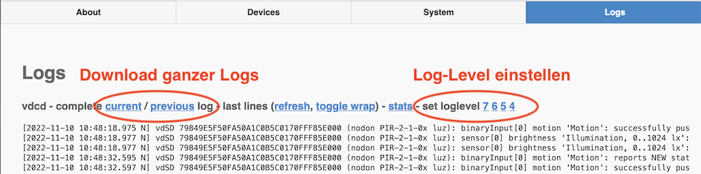
By default (after reboot) log level 5 is set, i.e. the messages with level 6 and 7 (info and debug) are not output. This results in not too many messages, but they make the basic activity on the device visible.
On each log line the corresponding level is written in the square bracket after the date as a letter, in the following example the "N":
[2022-11-09 18:17:51.492 N] vdSD 72536785B63C6CD8807428477EE2909600: changes to PRESENTLog download.
Using the links "current " and "previous " (see screenshot above), the current and previous logs can be downloaded as a whole (depending on the browser, it will be displayed as text in a new tab or end up in the download folder).
- The available memory for logs is limited. If there are many new messages, older log parts will be deleted. If the log level is set high (6 or even 7) this can happen relatively fast, and the log may only go back a few minutes. Normally (level 5), the log goes back one or more days.
Focus on a problematic device.
Sometimes you want to monitor a specific device, but don't want to set the log level higher overall because otherwise the log will be flooded with too many messages.
-
Since firmware 2.5.0 there is the LogLevelOffset for this purpose: If the info (i) button is pressed with the shift key held down (or on a tablet: held down for a long time), an additional line appears in the info dialog:
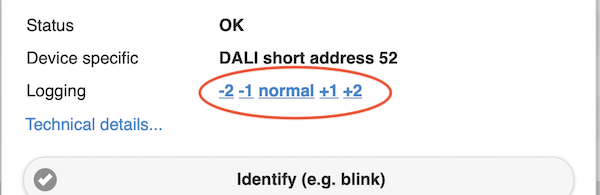
-
With click on "+1" or "+2" the corresponding device can be made "chattier", and vice versa with "-1" or "-2" also quieter (for the case that e.g. a single fast changing sensor, e.g. a wind sensor, fills the log although one would like to observe something completely different).
DALI
General
-
DALI, properly wired and operated with proper equipment is a simple, very reliable technology.
-
DALI can be implemented as a bus or star, or mixed with two wires, which can also be part of a multi-core cable with low voltage. The DALI connections on the P44-DSB are appropriately insulated and tested for safety.
-
Up to 64 ECGs/LED drivers can be connected to one DALI bus. Older color dimmers, however, may occupy a DALI address for each color channel and count several times accordingly. Modern so-called DT8 color light drivers, on the other hand, occupy only one DALI address despite several color channels.
-
The operating voltage of approx. 14.5V is provided by the P44-DSB-DEH. The supply is short-circuit proof. The polarity of the DALI bus does not matter (but is written on the device for information). No external DALI power supply may be connected additionally.
-
Good wiring is important. Poorly clamped contacts give transition resistances and cause voltage drop. If the voltage at a DALI device is below 12V, the bus will not function reliably (see Measure DALI bus)!
-
Particular care should be taken with conductor rails. The contacts of conventional multiphase rails are often not designed for operation with low voltage (DALI ~14V) and sometimes have too high contact resistances due to soiling from dust etc., somewhat worn clamping devices or not 100% correct latching/clamping. This usually does not interfere with operation with 230V, but can prevent the DALI bus from functioning correctly.
-
External voltage on the DALI bus can damage the P44-DSB, e.g. direct application of mains voltage between the DALI terminals or an external DALI power supply.
-
The P44-DSB is designed to integrate DALI LED drivers and ECGs into Digital Strom. DALI input devices (e.g. buttons, rotary dimmers or color wheels, but also light sensors) are not supported due to their operating principle, which is sending commands directly to the DALI drivers rather than to transmit data to a higher-level control system like Digital Strom.
-
The DALI bus has a very slow data rate by today's (and even then, DALI was invented around 2000) standards. The bus can only transfer 1200bits/second (for comparison: Ethernet has at least 1000000 bits/second, gladly 10 or 100 times more). This is not noticeable in operation, and makes the DALI bus robust and uncomplicated in wiring.
-
If the DALI bus is scanned, i.e. each connected device is found and queried for its details, then this can take a very long time due to the low data rate, with a fully loaded bus (64 devices) quite more than 10min. The scanning process should also not be interrupted if possible, because this can lead to incorrectly detected devices and tedious subsequent errors.
-
So some patience is needed when setting up DALI! Hectic plugging and unplugging, quickly repeated restarts or re-triggering scans via the web interface rarely leads to the goal, but rather causes further problems.
DALI bus failure
If the DALI bus fails, e.g. the power supply to a P44-DSB fails or the fixture itself has a defect, then DALI luminaires go to a preset default brightness. For most DALI drivers, this emergency brightness is set to 100% in the factory. This makes sense for safety reasons (sudden light is safer than sudden dark).
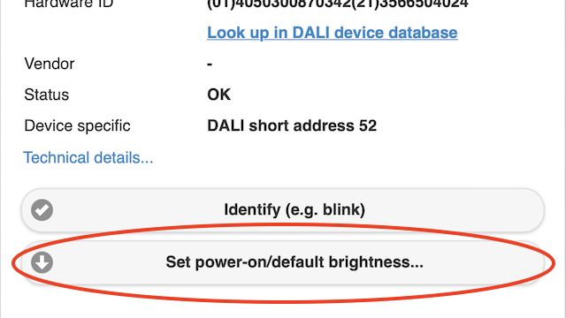
Depending on the application, however, an emergency brightness of 100% may be undesirable, e.g. in bedrooms, etc. Therefore, the standard brightness can be reprogrammed for each DALI device via P44-DSB:
- Set the luminaire(s) to the desired brightness (or completely off) in the event of a DALI bus failure.
- Open the info dialogue for each luminaire via the (i) button.
- Press the "Set power-on/default brightness..." button, see picture.
- Confirm in the following dialogue.
Default brightness is stored in the DALI device
This standard brightness is not a setting of the P44-DSB or Digital Strom, but is stored directly in the DALI device. device. If the unit is removed and used elsewhere, this setting is retained on the unit.
Selection of DALI devices
The unique identification.
-
Digital Strom (and any other modern system) needs a unique identification of the connected devices. For Digital Strom terminals this is the dSID or dSUID, each individual terminal has its own unique ID.
-
In the case of DALI, the concept of a unique identification was indeed laid down in the standard, but unfortunately ignored in practice by many manufacturers and apparently also not checked by the DALI certification test. Even today (2022), many DALI devices are still not standard-compliant on this point because they do not have a unique identification. The P44-DSB shows this fact in the status column of the device list:

-
Devices without unique serial number can be distinguished by the P44-DSB only by one feature, and that is the DALI short address. But this is neither unique (when installing not 100% brand new devices, several devices with the same short address can easily come together) nor stable (the short address is changeable). If an installation is configured once correctly and is not changed any more, also the short addresses do not change, and behaves also over long time stably. However, if additional DALI devices are added later, there is always a risk that devices without a stable serial number will appear mixed up in the dSS afterwards.
Therefore: For a really long-term stable DALI installation that can be expanded without problems, the following applies:
-
Whenever possible, use DALI devices with unique serial numbers. DALI2 certified devices have a better chance of having a correct serial number, but no guarantee.
-
In the P44-DSB and in the dSS, devices with unique serial numbers can be recognized by the fact that they have a so-called SGTIN as hardware ID, a number that contains both the manufacturer code and the serial number, in the form
(01)4050300876543(21)365123467. This has the further advantage that from this number the manufacturer and further information about the driver model can be found - in the P44-DSB info dialog these DALI devices have a corresponding link which directly calls the correct page in the DALI device database. However, not all DALI devices are listed in the database.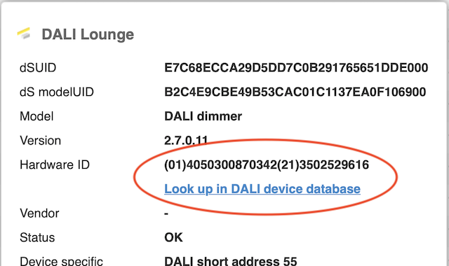
Unfortunately Serial Number botched, even with DALI2
Unfortunately, not even the DALI2 certification gives 100% certainty that the "unique serial number" (as required by the standard unequivocally) is really unique. It happens (fortunately very rarely) that two units of the same device model have the same serial number, even for DALi2 certified devices. If the two devices are connected to the same P44-DSB, it will detect this and treat the serial number as invalid; but if the two are on different P44-DSBs but in the same Digital Strom installation, they get the same dSUID and the dSS sees only one device.
Multi-channel or DT8?
-
The more modern so-called DT8 drivers for Tunable White (cool/warm white) and solid colors have the advantage that they occupy only one DALI address despite 3,4 or even 5 color channels (RGB, RGBW, RGBWA), which makes up to 64 color lights possible on a single P44 DSB.
Since DT8 is quite complex, there is still the risk of not fully developed firmware, especially with no-name DT8 dimmers, which may lead to misbehavior.
-
However, the P44-DSB also supports the "assembly" of several single-channel DALI dimmers (possibly housed in the same enclosure) to form an RGB, RGBW or RGBWA luminaire. Apart from the fact that this solution requires several DALI short addresses, nothing else speaks against it. The P44-DSB contains all the necessary color management, so even such a luminaire in the system behaves the same as one with DT8 ballast.
Recommended commissioning steps.
For the smoothest possible installation and maintenance - as mentioned above: Use DALI driver with unique electronic serial number!
If exclusively DALI devices with unique serial numbers are in use on a bus, there will be no problems with swapped luminaires in the dSS, and then the bus can be completely rescanned at any time without the slightest concern, and DALI drivers can be added or replaced at any time. However, if DALI drivers without correct serial numbers are in use, the following step-by-step procedure is recommended:
-
wire DALI installation as completely as possible, do not yet connect P44-DSB to the DALI bus.
-
function check of luminaires still without connecting DALI bus to P44: all should light up when supply is present (except for non-factory new devices, which may have been configured to a different switch-on brightness, as described here). If a luminaire remains dark: Check wiring. 3.
When the DALI bus is completely wired: check that there is no external voltage on the bus. **External voltage can lead to a defect in the P44-DSB!
Only now connect DALI to P44-DSB and then start/restart. 4.
-
Patience after restart, especially with many DALI devices and if many of them are DT8 luminaires (more data to transfer). A complete scan of a full bus will take 10min or longer. DALI has a very low data rate and takes time! Hectic restarting, resetting, etc. does nothing.
-
Don't start immediately with assigning in dSS! Also don't start with forming DALI groups, etc. This work is for nothing when, because of address conflicts, the bus must be completely rescanned and the short addresses (partially) reassigned.
-
If under "Devices " on the "DALI " line under Status you get an orange error message because of "Address collision " (move the mouse pointer over it to read the whole text), this means that several devices on the bus have the same short address. If not exclusively brand new DALI devices were used (but maybe already used in another (test-)installation), this can happen and is not a real problem at this point. In this case:
- Under "Devices" → DALI header → "(i)" button → "Scan for devices..." → "Service-only scans..." → "Force full re-scan of all devices " trigger.
- Again patience, may take a bit longer than a normal scan.
- Under "Devices " on the "DALI " line there should now be no error displayed.
-
Briefly test the basic function of each dimmer, preferably in the P44-DSB interface:
- "Devices" → DALI header → "(i)" button → "DALI bus diagnostics... ".
- For each DALI driver a green field should appear (compare number with actual installed devices).
- Pressing yellow button "all lights off " must switch off all lights connected to the bus, just as "all lights max brightness " must switch them all on.
- Clicking on a green field must make a light fully lit for a short time and then go to minimum brightness (not off).
-
If up to here something does not work, the error must be searched and found (mostly: bad DALI contacting, too much voltage drop, possibly wiring error, see below)! As long as the lights don't work properly on this level, no further configuration in P44 or dSS makes sense!
-
Optional: Use the "gear " button of the lights to call the brightness slider (for color lights additionally slider for color temperature + color) and test if the lights react as expected.
-
If everything works as expected, you can assume that everything is correct on the DALI + P44-DSB level. Now the luminaires should also appear in the dSS, and can be given names and room assignments.
-
If in the dSS the fixtures do not appear or are grayed out, although they are in the list in the P44-DSB, it is more likely due to an unreliable connection to dSS or general network problems.
-
If it took a force full re-scan (see above), then there are probably excess grayed out lights visible in dSS. These can be deleted.
-
It is worth to compare the number of lights in the dSS with the number of lights in the P44-DSB, if they are not the same, something is still wrong. But first reload the list on both sides, so that the display is really up to date.
In the P44-DSB:
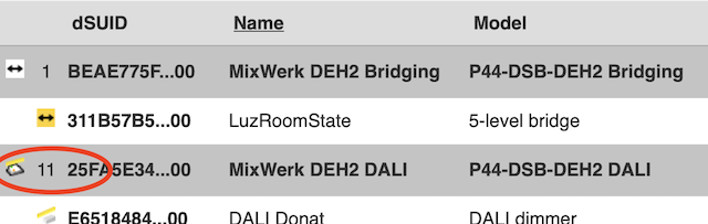
In the dSS:
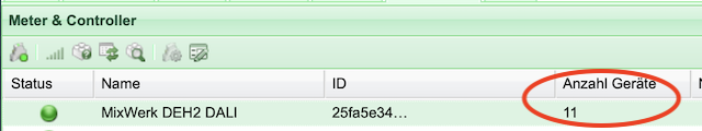
-
-
only when everything is working properly, also via dSS, you can consider turning on the optimizer, if with larger groups of lights the reaction looks too much "running light" (one after the other).
Documentation of the installation.
It is very useful to have documentation of an installation (and besides, of course, always: a backup of the configuration).
If the commissioning was successful and the luminaires have been assigned names, it is therefore recommended to have a "DALI Hardware Summary" created for this purpose. Apart from a bit of waiting time (slow bus scan) this costs nothing and is extremely useful for later troubleshooting or for sending along with support requests.
The "DALI Hardware Summary" can be triggered via the corresponding button "Devices" → DALI header → "(i)" button → "DALI Hardware Summary... ". A separate browser page will pop up, if the bus is full it may take several minutes until the result is displayed:
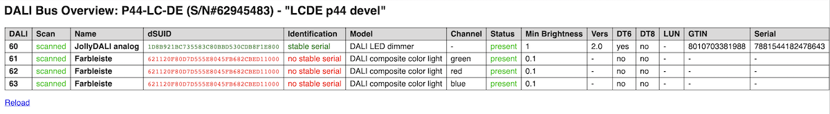
The appearing table contains all important information about all devices on the bus:
- the DALI short addresses of all devices
- the assigned names
- the dSUID
- The quality of the identification (see also above) - if it says "stable serial", then confusion after changes to the bus or complete re-scans is impossible, otherwise caution is advised.
- Possible groupings and color lights composed of single dimmers are visible, the column "channel" then shows the color channel (see "color bar" in the example).
- The Min Brightness (minimum brightness) - not so great dimmers sometimes have a high value here, i.e. cannot dim down too far.
- DT6 and DT8 indicate which features the DALI device has. DT6 is currently not (yet) relevant for the P44-DSB, DT8 means support for colors (cold/warm white or full color).
- The column LUN (Logical Unit Number) is interesting for DALI drivers which have several DALI dimmers in the same housing - of course the device has only one serial number, the single dimmers are distinguished by the LUN (which then appears in the last two digits of the dSUID).
- If available, the much mentioned electronic serial number consisting of GTIN (EAN) and the actual serial, at the very back of the table.
Keep this browser page printed or saved as a PDF with the project documentation.
Recommended procedure for adding to existing installations.
If an installation contains only DALI drivers with unique electronic serial number, and the newly added DALI devices also have an electronic serial number, they can simply be connected, and the P44-DSB restarted, and if there are any address conflicts (only happens with non-factory added devices), a "Force Full Re-Scan" can be triggered. There will be no confusion, all dSUIDs will remain stable, and the new fixtures will appear in addition.
However, if DALI drivers without serial number are in the installation or such are added, the following procedure is recommended:
-
DALI hardware summary of the current situation retrieve as a basis.
-
unplug DALI bus at P44-DSB (or de-energize everything, incl. P44-DSB).
Connect new DALI drivers/luminaires. 4.
Leave DALI bus unplugged, (re)start P44-DSB until it is ready (LED lights up green, possibly with occasional short yellow flashes). 5.
For safety: Check DALI bus for external voltage before connecting to P44-DSB. **External voltage can lead to a defect at the P44-DSB!
Only now connect the DALI bus. The P44-DSB does not make an automatic scan, the list of DALI devices therefore remains empty.
-
"Devices" → DALI header → "(i)"-button → "DALI bus diagnostics... ", and check basic DALI function (as described above at commissioning steps).
-
If there are orange fields here, then there are address conflicts, and it needs a "Full Rescan". If all fields are green, there is probably no address conflict, but it is not completely sure.
-
Comparing with the "DALI-Hardware Summary" you can quickly see which DALI short addresses have been added.
-
By clicking on the new green fields you can see if the new luminaires work and if an existing luminaire has an address conflict and reacts. If this happens, it needs a "Full Rescan".
-
Factory new fixtures do not have a short address yet, so they do not have a green field yet. This is not a problem, they will get a free short address during the scan (see next point).
-
if no address conflict was detected, a normal scan is now sufficient: "Devices" → DALI header → "(i)" button → "Scan for devices..." → "Normally re-scan and re-register all devices ". After that, all the previous devices and the new ones should appear in the list and, with some delay, in the dSS.
If address conflicts are detected, a "Full Rescan" is needed. It can happen that a newly added device without electronic serial number is mixed up with a previously installed one without serial number - then you have to correct the names and room assignments in the dSS accordingly.
-
otherwise, the general commissioning instructions apply, see above.
-
even after a change, documentation of the new state with a "DALI hardware summary" is recommended.
Optimizer
Because the DALI bus has a very low data rate, in rooms with many DALI luminaires, you see a "running light effect" when scenes are called, especially when colored luminaires (which need more data) are involved.
Since the beginning, the P44-DSB offers the possibility to manually form groups so that several DALI dimmers appear as one Digital Strom luminaire in the system. The disadvantage is that the dimmers then run in parallel in any case and can no longer be controlled individually at all.
Therefore, in most cases the "Optimizer" is the better solution. This automatically forms DALI groups and DALI scenes (max. 16 each) for frequently used Digital Strom scenes, which can then be called up perfectly synchronously. The optimizer keeps statistics about the different scene settings and the number of affected luminaires, and assigns scenes to the most frequent combinations (after at least 4 calls). Combinations that have not been used for a long time are released again over time for newer, frequently used ones.
The settings for the optimizer can be found under "Devices" → DALI header → "(i)" button:
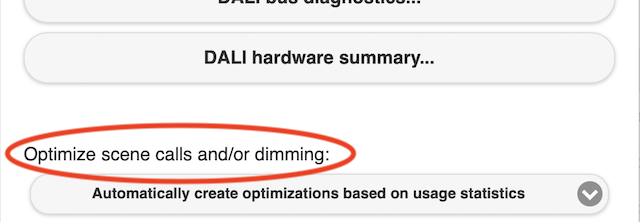 .
.
The following settings are available:
Optimization disabled Default setting: Optimizer disabled. In case of problems (luminaires react wrong on scene calls), select this setting first.
- Use existing Optimization
- The optimizer uses the previously learned scenes, but does not learn anything new. This can be used to freeze a proven situation and protect it from changes. But if the dS-scenes are changed, the optimizer won't work with time because the saved scenes don't exist anymore. Before that the setting "Automatically create optimizations..." must have been used for a while, otherwise this setting has no effect.
- Use existing Optimization, update when scenes are changed/saved
- The optimizer uses the previously learned scenes, and adjusts the settings when the scene settings are changed, but does not create new scenes or delete existing ones. The setting "Automatically create optimizations..." must have been used for a while before, otherwise this setting has no effect.
- Automatically create optimizations based on usage statistics
- This is the recommended normal setting. This is the recommended normal mode. The optimizer keeps statistics on the digitalSTRIOM scenes called and makes sure that a DALI scene is used for the most used ones (3 lights or more), so that the lights switch perfectly in sync.
- Clear Optimizer Cache (but no mode change) - use with care
- When this option is clicked, the optimizer cache is cleared, i.e. all existing optimizations are removed, and learning starts again. The optimizer mode is not changed by this.
If the log is set to at least level 6, a statistic of the scene calls appears after each optimized scene call, the line with the asterisk is the one affected by the current scene call.
[2022-11-30 20:16:50.913 N] Optimizer statistics after 88 optimizable calls for vDC 25FA7890CFB75913800265EE292CB2AB00 (office DALI):
- 'callScene' called 7 times (weighted, raw=7), last 23 seconds ago, contentId=0, numdevices=7, nativeAction='DALI_scene_1'
* 'callScene' called 3 times (weighted, raw=3), last 21 seconds ago, contentId=5, numdevices=7, nativeAction='DALI_scene_0'
- 'callScene' called 4 times (weighted, raw=4), last 79515 seconds ago, contentId=0, numdevices=5, nativeAction='DALI_scene_2'
- 'dimChannel' called 9 times (weighted, raw=10), last 79531 seconds ago, contentId=0, numdevices=5, nativeAction='DALI_group_1'
- 'callScene' called 5 times (weighted, raw=5), last 6932 seconds ago, contentId=72, numdevices=11, nativeAction='DALI_scene_3'
DALI debugging.
General procedure
-
if luminaires react differently than expected when scenes are called and the DALI optimizer is switched on, as the very first measure, switch off the optimizer. With the optimizer switched on, troubleshooting is very tedious. If afterwards the lights react correctly again, the optimizer should be reset, but can usually be used again afterwards.
-
if connected lights do not appear at all in the list of P44-DSB:
- Ensure that the power supply is correct. With a weak/unsuitable power supply or an incorrect PPoE supply, the unit may appear in the network but not be able to control the DALI bus correctly!
- Test if the luminaire responds to DALI commands at all: "Devices" → DALI header → "(i)" button → "DALI bus diagnostics... " call up.
- Pressing the yellow button "all lights off " must switch off all luminaires connected to the bus, just as "all lights max brightness " must switch them all on. A light that does not react here is defective or not correctly connected to the bus. In this case: check / measure DALI bus wiring.
- Are more than 64 DALI devices connected? Attention, simple multi-channel dimmers without DT8 may occupy one address for each channel. More than 64 addresses on the same bus are not possible!
- If the lights react at "all lights max/off": Rescan bus with "Devices" → DALI header → "(i)" button → "DALI bus diagnostics..." → "Scan for devices..." → "Look for new devices only... ". This will search again on the bus for devices not found so far. Patience, this can take 10min and more with many devices on the bus.
- If the fixtures are now still not in the list: check / measure DALI bus wiring.
- Also take a look at log, possibly error messages are visible. 2.
-
if connected luminaires appear in list of P44-DSB, but are grayed out, this means that the luminaire was correctly addressable at the last restart of the P44-DSB or at the last bus scan, but not anymore.
- This points most likely to a loose contact
- e.g. with DALI bus via conductor rails, which are not explicitly suitable for low voltage buses, there may be high contact resistances at the contacts - latching/unlatching and moving them a bit may help. Also see here.
-
if the connected lights appear in the list of P44-DSB, and are not grayed out: Press gear button and use sliders to check luminaire operation. If the fixture responds correctly here, but not via scene calls or from the dSS, then it is not a DALI problem, but rather a connection problem between P44-DSB and dSS.
DALI bus wiring.
Possible bus problems are:
-
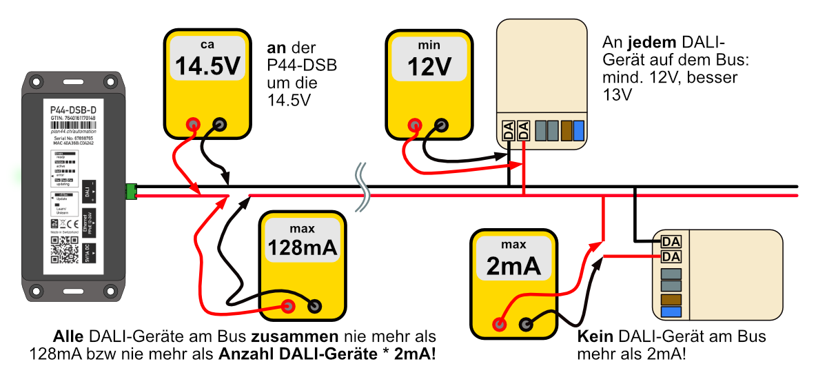
if the wiring has too high contact resistances (bad contacts) and as a result the voltage drop between P44 and (one, or more) DALI devices on the bus becomes too large. At least 12V must be present between the DALI connections of each device otherwise proper functioning is not guaranteed. 2.
-
if one or more DALI devices are defective or "cracked" and put too much load on the DALI bus. A single DALI device may not draw more than 2mA current from the bus, the whole bus in total not more than 128mA (or number of devices * 2mA), see "Measure DALI bus" If these values are exceeded, especially the bus scan (reading data from the DALI devices) will not work properly. But it may be that the control via "Devices" → DALI header → "(i)" button → "DALI bus diagnostics..." → "all lights max/min/off... " still works, so this is not a guarantee for a proper bus!
-
if the bus has a short circuit somewhere. Normally the P44-DSB detects this and displays it as an error message, but if this happens combined with poor contacting and correspondingly high voltage drop, not necessarily.
-
if the bus once had external voltage when the P44-DSB was connected. This can lead to a defect in the P44-DSB (internal chip fuse, usually repairable but the device must be sent in).
DALI bus measure
Measurement when bus is active is not meaningful
If a bus scan is running, or scenes are called continuously, then measuring bus voltage and current is not reliable. Wait until scans are completed. The LED on the P44-DSB should be green, not flickering wildly yellow/red.
The DALI bus voltage is DC
Use DC setting on the meter accordingly. AC measurement may also show something if the bus is not completely at rest, but nothing meaningful.
If DALI bus problems are suspected, the following should be measured:
-
first, easiest to measure quickly: the voltage at the P44-DSB, at the green terminal. If it is lower than about 14.5V, disconnect the DALI bus and measure again at the P44-DSB to make sure that the power supply to the P44-DSB is working.
- if without connected bus no voltage can be measured, then the P44-DSB is defective (probably internal fuse blown by external voltage, can usually be repaired)
- if the voltage without bus is ok and only with connected bus no or very little voltage can be measured, then the bus has a short circuit somewhere.
- if the voltage drops below 14V with the bus connected, but is at about 14.5V without the bus, one or more devices on the bus is drawing too much current -> measure bus current.
-
if voltage at P44-DSB is too low: measure total bus current, one DALI wire must be disconnected at P44-DSB: The total current must not be more than 128mA, or not higher than number of devices times 2mA. So for a small bus with 4 DALI devices already 20mA are too much (4*2mA = 8mA max.) If the current is higher, most likely one of the DALI devices is defective and draws too much current. The faulty device must be found and removed, it also interferes with the communication of all other devices.
-
if the total current is too high: a single DALI device must never draw more than 2mA current from the bus. Modern DALI devices usually draw much less, more in the range of 0.2mA. Depending on the wiring, the current can be checked at individual devices, or parts of the bus can be measured to find out which device is drawing too much current. 3.
-
if the voltage at the P44-DSB is correct and the total current is not too high: measure the DALI voltage at unrecognized or not properly working dimmers/drivers, and at the farthest connections. This should be at least 12V everywhere, better higher. If the voltage is lower, there are probably bad contact points/terminals in between on the bus causing voltage drops; these need to be found and fixed. In particular, conductor rails that are not explicitly designed for low-voltage bus signals can be problematic, see also here.
Enocean
General
-
EnOcean is a wireless standard that was designed from the beginning to be battery-free sensors and pushbuttons. The necessary energy is obtained either from mechanical energy (operation of pushbuttons, movement of contacts), heat (in the case of heating valves) or even light (solar cells). However, there are also mains-powered EnOcean devices, and also those with batteries.
-
EnOcean uses the 868MHz band in Europe. In other markets there are also 315MHz and 902Mhz, but such modules are not compatible with the P44-DSB.
-
The radio technology and often the power source in almost all products comes from EnOcean itself. Also the radio module in the P44-DSB is one of Enocean, the TCM310. Although there are e.g. innumerable manufacturers of switches, the technical module in it is with nearly all the same (PTM215). The advantage of this is that there are hardly any incompatibilities, because the basic modules are always the same. Enocean has thus become a very reliable, not overly complex building radio standard for long-life installations.
-
Each device has a unique serial number, written as an 8-digit hex number: e.g. FEFFA86B or 0183DB7E. This is displayed in the P44-DSB and also in the configurator as hardware ID. In the case of multiple units (most common example: the pushbutton with two rockers), the units are distinguished in the configurator with an additional number, e.g. FEFFA86B-1, FEFFA86B-2. Because the serial numbers are always present and always unique, with EnOcean (unlike certain DALI devices) there is no confusion. An EnOcean device always appears everywhere with the same ID and also dSUID.
-
The protocol consists of short so-called radio telegrams. A special feature is that in many cases the end devices decide when to start radio traffic. So it is not possible to read e.g. a sensor value at any time, but the sensor sends e.g. by itself every 10min, possibly even only every 40min a value. This also applies to heating valves - these cannot be adjusted at any time, but 10-20 min pass until the valve sends a telegram of its own accord - and only at exactly this time can it receive a telegram with a new control value. Therefore, one does not see/hear immediately whether a positioning command from the dSS is executed by the valve, but 10-20min later. EnOcean devices, especially sensors, usually have few or no settings, but are built for a specific purpose.
Device compatibility, profiles
-
EnOcean devices support one (or sometimes several) so-called EnOcean Equipment Profiles (EEP). The profiles are designated with an EEP number like A5-20-01.
-
Older devices or their documentation sometimes still use an older notation of the profile numbers:
- instead of A5-xx-xx there is 07-xx-xx
- instead of D5-xx-xx there is 06-xx-xx
- instead of F6-xx-xx it says 05-xx-xx But they are the same profiles, for compatibility the spelling does not matter.
-
On the plan44 website the EEP numbers are listed, which are currently supported by the P44-DSB. The list will be extended continuously when new firmware supports new profiles.
-
Only the EEP number is decisive for compatibility - often there are different devices, manufacturers, designs for one and the same profile. Mostly the profile number is visible somewhere in the datasheet of a device, but sometimes you have to ask the manufacturer.
-
For many profiles the function is unique, but for some (especially F6-xx-xx) there are for the same profile number different purposes and variants. For these, a corresponding selection appears under "Devices" → Device line → "(i)" button → "Device has multiple configurations ".
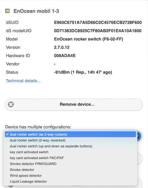
A smoke detector therefore appears e.g. after teach-in first as a pushbutton, and must be changed manually to the smoke detector configuration. Pushbuttons can also be used in different ways, e.g. as up/down rockers or as single pushbuttons. The selected configuration is stored in the P44-DSB, and not in the EnOcean device itself.
Teach-in and teach-out.
For learning and unlearning, the P44-DSB is put into learn mode, i.e. it listens until a learn telegram is received, and then remembers the Enocean address, or deletes it if it was already stored previously.
EnOcean devices can also be removed from the system via the web interface: "Devices" → Device line → "(i)" button → "Remove device... ", instead of unlearning them.
!!! warning "Unlearning is not the same as deleting". When deleting via the web interface, the device is removed from the system and all associated configuration is deleted (name, Digital Strom group/color etc.). When unlearning, the device is also removed, but the configuration is retained, i.e. when the same device is taught in again later, it is configured as it was before. When deleting via the web interface, only the relevant element is deleted for devices with several elements (e.g. pushbuttons), the others are retained. When unlearning, all elements of the unlearned device disappear.
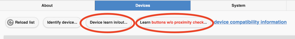
Pushbuttons and simple sensors (F6-xx-xx and D5-xx-xx)
These devices do not know a separate learn mode, but send the same telegram each time they are actuated.
If, during the teach-in process of a pushbutton in the vicinity, another pushbutton is accidentally actuated, then this could be taught-in by mistake.
To prevent this from happening, these devices are only taught-in when a sufficiently strong radio signal is received from them, i.e. when the device is approximately within 30cm or closer to the P44-DSB.
If for some reason the device can not be brought that close, you can do the teach-in on the web interface without the "proximity check" (w/o proximity check, button with red writing on the right), with the risk that another device will be taught in by mistake.
Remove superfluous button halves
Almost all buttons contain the same module (PTM215), which has contacts for two pushbuttons (or 4 single pushbuttons). Only the pushbutton caps make the difference whether two rockers or only one is actually available for the user:in. After teach-in, EnOcean pushbuttons always appear as 2 separate rockers - but with a single pushbutton, the second rocker remains without function, and can be removed via the web interface.
Other devices (A5-xx-xx and D2-xx-xx)
These devices send a separate learn action (triggered by a special button, magnetic contact, etc.) that is different from normal operation. Mains-powered devices sometimes send the learn action once after the supply voltage is applied. Details of this must be found in the manufacturer's documentation.
Therefore, the radio signal strength is not evaluated for these devices, i.e. they can and should always be taught-in and taught-out normally (button without red writing)!
Encryption
Newer EnOcean devices support encrypted connections. Even if the Encean hardware ID of a device is known, these cannot simply be tapped or simulated by an attacker with a jammer. Otherwise, they function in the same way as unencrypted connections.
-
The usual pushbuttons with the PTM215 module can be switched between unencrypted and encrypted by removing the pushbutton cap and performing a special click combination on the contacts underneath. Some manufacturers offer an "encryption rocker" which helps with the necessary multiple clicks.
-
On other devices, the teach-in action can be started with or without encryption (hold the teach-in button longer or shorter, or press it multiple times, etc.). There are different procedures, the details have to be read in the documentation of the respective manufacturer. With some devices it is a bit of a skill game to get the teach-in sequence right - the manufacturer's instructions must be followed very carefully for it to work.
-
A device learned with encryption cannot be downgraded to unencrypted without first deleting it via the web interface.
-
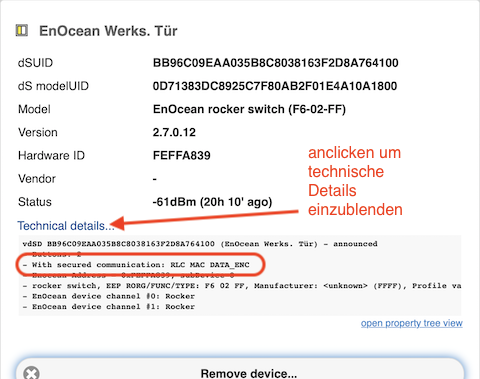
Whether a device is connected encrypted can be seen under "Devices" → Device line → "(i)" button → "Technical detail... ", if it says "With secured communication", then the connection is encrypted:
Ranges, signal strength, measuring
-
Problems with EnOcean are mostly related to radio propagation.
-
The range of EnOcean can vary greatly depending on the environment. In the package inserts of devices there are often some hints for proper placement.
-
Useful more detailed information on range planning is provided by EnOcean in an application note.
-
The range can be increased with so-called repeaters ("repeaters"), which receive all telegrams from the environment and retransmit them with full signal strength. With EnOcean, a maximum of 2 repeater stages are possible. Repeaters have as the only configuration (usually via a switch) the setting whether they work as 1st stage or 2nd stage.
-
A signal going through repeaters is delayed a bit (and a bit more if there are 2 stages). This is mostly uncritical for sensors, but can be neagtively noticeable for pushbuttons (especially multi-click or dimming).
-
To judge the signal strength in the overview, the P44-DSB shows in the status column under "Devices " the signal strength (RSSI) of the last telegram (not continuously updated, reload list to see current values). The status is shown in green when the signal strength is good (in the range -60..70dBm), and moves towards red when the signal strength is weak (towards -90dBm). However, the status can also be shown in red if e.g. the supply voltage is too low or there is some other problem.
-
To evaluate a single device: Open info window via "Devices" → device line → "(i)" button. Here the status is displayed as well, and the display is automatically updated every few seconds. For example, you can use a button to move around a room and click in different places, observing the status to get an impression of the radio propagation.
-
The status shows signal strength (RSSI) of the last received telegram and the number of repeaters it was relayed through. Examples:
-91dBm (1 rep, 1h 42' ago)- A weak signal
-91dBmforwarded through a repeater1 Rep.one hour and 42 minutes1h 42'ago. -51dBm (25" ago)- A very good signal
-52dBm, received directly 25 seconds ago.
-
A weak signal does not necessarily mean that it is too weak. As long as it is detected and displayed by the P44-DSB, it will work. A weak signal is only a hint that (due to fluctuations) not every telegram could arrive safely. Only if the displayed time since the last received signal is longer than expected from the documentation of the device (interval varies depending on the sensor, documentation of the device should provide information, usually 5-20min) a repeater or an external antenna may be recommended.
-
A repeater will only be visible in the status (
1 Rep.or2 Rep.) if it is actually used, i.e. only if the P44-DSB could not receive the original signal. As long as the P44-DSB receives the signal directly, even if it is weak, that is ok. Therefore: if a repeater is installed because of a weak signal, it does not immediately change the picture in the status display - but it still fulfills its function, because it just forwards the signals that otherwise would not have arrived at all, and so the system becomes more reliable.
External antennas on P44-DSB-DEH2 and P44-DSB-E2.
-
Depending on the mounting position of the P44-DSB, an external antenna set off with cable instead of the supplied rod antenna can improve radio propagation, mostly because the external antenna can be better aimed.
-
In principle, any antenna suitable for 868Mhz with SMA-M connector can be used, e.g. this model (CH supplier) or this model (China direct).